
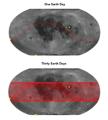
Figure 4 Lunar orbiter track and simulation analysis locations.
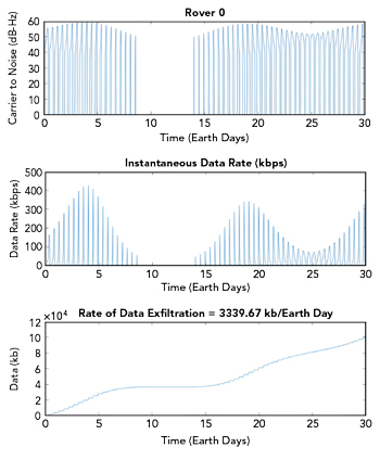
Figure 5 Single orbiter pointed at Rover 0, other rovers not transmitting.
Figure 4 identifies three hypothetical rover locations to be used in the simulations. The location of Rover 0 is at the proposed location for Lunar Surface Electromagnetics Experiment Night. The location of Rover 1 is at the South Pole at an upcoming planned lunar mission site and the Rover 2 location is on the near side in Mare Crisium.
Figure 5 shows the simulation results for Rover 0 pointed at a single orbiter with no other rovers transmitting. The top subplot shows the carrier-to-noise density over time, the middle subplot shows the data rate over time and the bottom subplot shows the total amount of exfiltration data over time. Figure 6 shows the same data presentation for Rover 1 pointed at a single orbiter with no other rovers transmitting. Figure 7 shows the data presentation for Rover 2 pointed at a single orbiter with no other rovers transmitting.
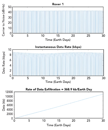
Figure 6 Single orbiter pointed at Rover 1, other rovers not transmitting.
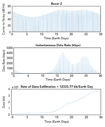
Figure 7 Single orbiter pointed at Rover 2, other rovers not transmitting.
In this hypothetical comparison, the orbital satellite and the rovers all have consistent and realistic link parameters, such as transmit power and antenna gain. They are kept constant across the data examples to make realistic comparisons. From the data plots, it can be observed that Rover 1 has the lowest exfiltration of the three. That is, Rover 1 can exfiltrate 0.37 Mb/day on average, while Rover 0 is able to exfiltrate almost 10x that, at 3.3 Mb/day and Rover 2 is able to exfiltrate the most, at 12.3 Mb/day.
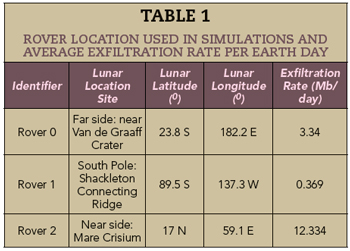
As the data shows, the location of the lunar lander can have a significant effect on the amount of exfiltration data that can be captured. Note that for some rover locations, the amount of data per pass can change significantly, as in the case of Rover 0. But for some rover locations, a pass is very consistent. This is the case for Rover 1, located at the South Pole. The three hypothetical rover locations used in the simulations and the resulting average exfiltration rates shown in Figures 5 to 7 are summarized in Table 1.
SINGLE ANTENNA POINTING AT THE LUNAR LANDER WITH INTERFERENCE
To illustrate the effect of unintentional co-channel interference, this section considers the case when the orbiter is communicating with Rover 1, but Rover 0 is transmitting in the same band. That is, Rover 0 is causing interference with Rover 1 communicating to the orbiter. This may be the case when Rover 0 is deployed from a country that does not participate in widely accepted spectrum allocations and standards. For example, in this scenario, the country may not have gotten approvals from the National Telecommunications and Information Administration (NTIA).
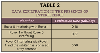
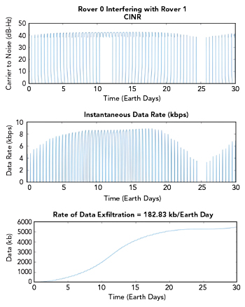
Figure 8 Rover 0 interfering with Rover 1 with the orbiter pointed to Rover 1.
In this case, Rover 0 degrades Rover 1’s performance. This is illustrated in Table 2. The instantaneous data rate and carrier-to-noise density are shown in Figure 8. Note that the interference from Rover 0 degrades the performance significantly on some passes and insignificantly on others. The overall performance reduces the exfiltration rate by over 50 percent of the non-interfering exfiltration rate. Specifically, without interference, Rover 0 was able to exfiltrate 0.37 Mb/day, but in the presence of interference, that result gets reduced to 0.18 Mb/day.
PHASED ARRAY ANTENNA POINTING AT THE LUNAR LANDER WITH INTERFERENCE
The other interesting result shown in Table 2 is the improvement in the data exfiltration rate when the orbiter has a phased array antenna, even when Rover 0 is interfering with Rover 1. For this application, Vulcan Wireless has developed the S-Band phased array shown in Figure 9. The phased array antenna is a smart antenna that autonomously determines the direction of arrival of both the desired source and the interference. The performance curves for Rover 0 interfering with Rover 1 when the orbiter uses a phased array radar are shown in Figure 10. Comparing the results of Figure 10 with the results of Figure 8, it is clear that the phased array improves the performance by more than an order of magnitude over the single antenna case in the presence of interference. The hardware for the phased array SDR and smart antenna leverages the flight-proven technology of a previous generation of phased array antennas.
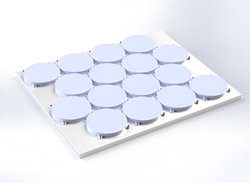
Figure 9 Vulcan Wireless S-Band phased array antenna.
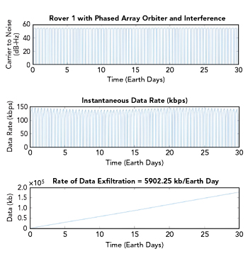
Figure 10 Rover 0 interfering with Rover 1 and orbiter using phased array antenna.
CONCLUSION
This article has discussed data exfiltration from the lunar surface back to Earth. It has looked at several cases to illustrate how the data exfiltration rate depends upon the location of the rover relative to the orbiter. A significant degradation in data exfiltration rate has been observed when a second rover is broadcasting its data to a secondary orbiter. However, introducing a phased array antenna on the orbiter increases the gain to the desired user and helps to mitigate the effects of the in-channel interferences. Even in the presence of interference, this architecture has been shown to increase the amount of data exfiltration by a lunar rover by more than an order of magnitude versus the best-case performance of a single antenna with no interference.