

AI is significantly impacting almost all engineering fields, but its potential is especially promising for antenna analysis and optimization to minimize the need for repeated full-wave electromagnetic simulations. Although AI models have proven effective in characterizing and optimizing various antennas, the field lacks a comprehensive framework for both standard and custom antenna solutions. To address this gap, AI techniques are applied to create scalable and generalizable models for antenna design and analysis, enabling adoption by engineers without expertise in electromagnetic theory or AI.
To support the design and optimization of a comprehensive AI-driven workflow with minimal specialized knowledge in machine learning (ML) and electromagnetics, engineers can rely on pre-trained ML, AutoML and optimization algorithms. The AI-driven approach, coupled with the pre-trained algorithms, accelerates the antenna design process. It also democratizes access to advanced design tools, allowing for faster and more flexible customization and performance enhancement.
RAPID ANTENNA ANALYSIS WITH PRE-TRAINED MODELS
For engineers, it begins with developing pre-trained AI models for antenna analysis while addressing the lack of commercially available design software with built-in AI capabilities. The approach consists of the following steps:
1. Catalog Standard Antennas: Begin with a set of standard antennas with parameterized geometries suitable for full-wave electromagnetic simulation.
2. Prototype Design Development: For each antenna, derive an initial design prototype using a combination of design variables (e.g., geometric parameters) to ensure resonance at a specified frequency.
3. Tunable Design Variables: Identify a subset of design variables that can be adjusted within specified tolerances (e.g., ±15 percent) to explore variations around the initial design point. Simulate how these adjustments affect key performance metrics.
4. Intelligent Sampling: Use intelligent sampling to create a dataset of simulations that represent the antenna’s design space.
5. ML Model Training: Train ML models to predict performance across wide parameter ranges with high accuracy and minimal computation time.
6. Frequency Scaling Generalization: Extend each prototype’s ML model to other initial design frequencies using frequency scaling principles.
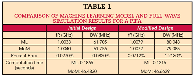
This strategy enables workflows for early-stage design exploration and interactive visual examination that were previously impractical. For instance, if an engineer needs a planar inverted-F antenna (PIFA) to resonate at 1 GHz, they can quickly generate a design blueprint. Using a pre-trained ML model to predict resonant frequency, engineers can efficiently explore and optimize dimensions such as length, width, height and short pin width to maintain the 1 GHz resonance. Once an optimal design is identified, full-wave electromagnetic simulations can verify AI predictions and guide further refinement. Table 1 shows a comparison of an ML model and full-wave simulation method of moments (MoM) results for a PIFA with dimensions adjusted by -9 percent in length, +12 percent in width, +5 percent in height and -4 percent in short pin width from the 1 GHz prototype. Full-wave simulations use a frequency sweep from 700 MHz to 1.3 GHz with 1 MHz resolution for resonant frequency and bandwidth analysis. As shown in Table 1, ML models provide results much faster than electromagnetic simulations. Parameter sweeps of a 1 GHz PIFA using the pre-trained regression ML model to predict resonant frequencies based on varying geometric properties are shown in Figure 1. These results illustrate that resonant frequencies for 2500 configurations can be predicted in seconds, facilitating rapid iteration during early-stage design without costly simulations.
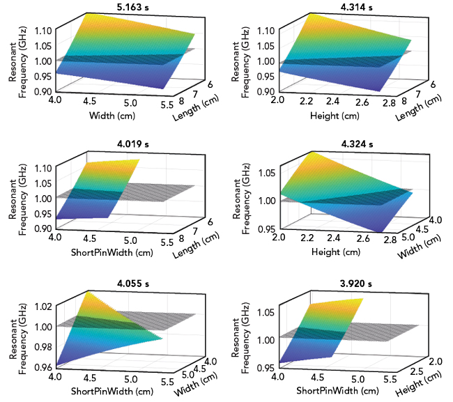
Figure 1 1 GHz PIFA parameter sweeps using the pre-trained regression machine learning model.
AI-accelerated parameter sweeps also help narrow the design space. In Figure 2, a pre-trained ML model classifies 2500 PIFA configurations based on 50 Ω matching. The impedance matching scenarios were determined for a PIFA antenna designed at 300 MHz. Each configuration varies in length and height around a PIFA designed for 300 MHz resonance. The results were predicted in under 10 seconds when using the pre-trained classification ML model.
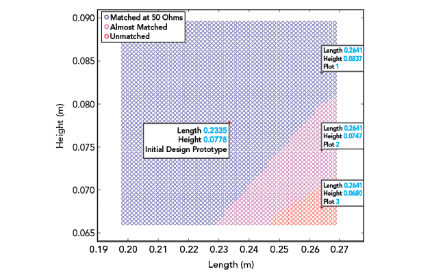
Figure 2 Impedance matching scenarios for a PIFA antenna designed at 300 MHz.
Figure 3 shows the full-wave electromagnetic verification of bandwidth and impedance matching conditions for the points shown in Figure 2. It verifies the classification of three designs against full-wave simulation, focusing on the “Plot 1,” “Plot 2” and “Plot 3” regions referenced in Figure 2. Although classification alone does not finalize the design, it indicates that a length-to-height ratio below 3.5 is necessary for matching. This refines the optimization space and improves efficiency for subsequent methods.
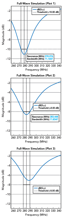
Figure 3 Full-wave electromagnetic verification of bandwidth and impedance matching conditions.
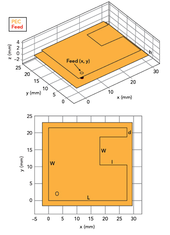
Figure 4 C-shaped microstrip patch antenna.
The scalability of this approach is demonstrated by the “AIAntenna” object in Antenna Toolbox, which provides access to pre-trained ML models for various catalog antennas, including PIFA and other patch antennas. This capability allows for rapid AI-accelerated parameter sweeps of standard antennas. This, in turn, enables quick analysis and categorization of design spaces, identification of optimal dimensions for specific performance goals and insights into the design space’s response surface.1