

AUTOML TRAINING CUSTOM ANTENNAS AI MODELS
AI models can extend their utility beyond standard antenna types (e.g., dipoles, patches and horns) to custom antenna structures. However, developing these models typically requires expertise across disciplines. Knowledge of antenna design and electromagnetic analysis is crucial for problem formulation, setting up measurement systems, identifying key parameters and interpreting results. Simultaneously, a background in statistics, design of experiments (DOE) theory and ML is necessary for implementing the training framework, sampling data, designing AI models and validating their performance with reliable metrics. This cross-disciplinary requirement can hinder the application of AI techniques for antenna design and analysis. Therefore, automation frameworks and low-code tools are essential. The general ML workflow involves:
1. Modeling and parameterizing the antenna for simulation
2. Defining design variables as predictors and metrics as responses
3. Conducting a DOE for sampling the design variables
4. Performing electromagnetic simulations to generate response data
5. Preprocessing and exploring data in preparation for training
6. Iteratively training and tuning ML models for optimal performance
7. Evaluating the ML model against simulation results for accuracy on new data.
This workflow is demonstrated by training an ML model to characterize a probe-fed C-shaped microstrip patch antenna2 and predict its resonant frequency based on its dimensions. Stochastic DOE methodologies and low-code AutoML for model selection, training and tuning are used for creating an antenna model. This is different from what was reported in other works. Figure 4 shows the parameterization of the C-shaped microstrip patch antenna with the nominal values for the design variables being: L = 24 mm, W = 20 mm, l = 10 mm, w = 7.2 mm, d = 2.4 mm and h = 1.6 mm.
The antenna is modeled with an air substrate, but the approach can be applied to dielectric structures. Design variables are varied within a ±25 percent range around nominal values, resulting in 200 data points. Each configuration is simulated from 1 to 4 GHz using a full-wave MoM solver to find the resonant frequency. The data is split 80 percent into training and 20 percent into test sets, covering steps 1 to 5.
AutoML automates step 6 of the ML workflow using the “fitrauto” function from the Statistics and Machine Learning Toolbox. This function performs regression model selection and hyperparameter tuning. It employs Bayesian optimization to evaluate ML models like Gaussian process regressors (GPRs), support vector machines and artificial neural networks, selecting a model with minimized generalization error.
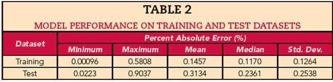
This results in a low-code solution. Step 6 is executed with a single line of code, producing a tuned GPR model with less than 1 percent prediction error on both training and test data. The model’s accuracy is detailed in Table 2 and visualized in Figure 5, providing both quantitative and qualitative assessments as per step 7 of the ML workflow.
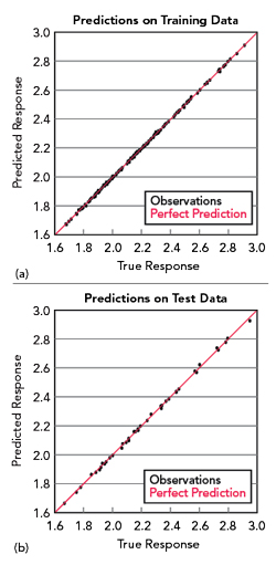
Figure 5 Model performance on training (a) and test (b) data sets.
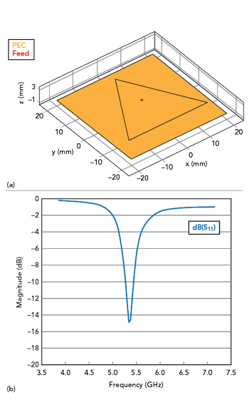
Figure 6 Probe-fed equilateral patch antenna (a) and simulated S11 (b).
EVOLVING THE ANTENNA SHAPE WITH SURROGATE OPTIMIZATION
Pre-trained AI models for standard and custom antenna structures provide valuable insights. However, surrogate optimization offers an alternative by learning subsets of the design space during optimization. As the surrogate model is developed and updated during the optimization, this technique can be applied to evolving antenna shapes where pre-trained models provide insufficient insights.
Traditional antenna optimization relies on full-wave electromagnetic analysis, which is resource-intensive in terms of time and memory. Strategies to mitigate solver complexity include higher-order basis functions, iterative methods like the fast multipole method, GPU acceleration and hybrid full-wave/asymptotic methods. Despite these, a single parameter set requires significant computational resources and exploring multiple design variables adds a combinatorial challenge. The search space often contains multiple extrema, typically framed as minimization problems. This necessitates either defining bounds to ensure a unique local minimum or employing global optimization techniques to explore the true solution space. Surrogate-based optimizers3 fall into the global optimization category but differ by reducing expensive electromagnetic solver calls. They build a surrogate model that initially learns the search space characteristics using the electromagnetic solver and then drives the optimization. To maintain accuracy, the surrogate’s outputs are occasionally verified against the electromagnetic solver. Any deviations in the outputs prompt updates with new true solution points, continuing the optimization while minimizing electromagnetic solver calls.
The use of surrogate optimization is demonstrated starting with a standard triangular microstrip patch antenna and evolving its shape to achieve a target performance objective. This surrogate-based approach is applied to enhance the bandwidth of a single-feed, probe-fed triangular patch antenna on an air substrate by evolving the side shapes.4 Initially, a standard probe-fed equilateral patch antenna is designed for the lower half of the 5 GHz band, with a -10 dB bandwidth of about 3 percent, as shown in Figure 6.
The surrogate optimizer aims to improve bandwidth to cover 5.0 to 5.6 GHz by adjusting the shapes of the three sides while leaving the corners and ground plane unchanged. Three Gaussian functions, defined in Equation 1, represent each side’s shape, introducing three optimization variables per side: mean (μ), standard deviation (σ) and scaling term (w).
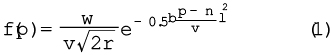
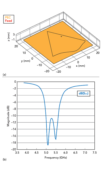
Figure 7 Evolved probe-fed patch antenna shape (a) and simulated S11 (b).
These three variables adjust the curve’s amplitude relative to the original edge, with p as the position along the side. The feed coordinates (x, y) add two more degrees of freedom, totaling 11 independent variables for the shape optimization.
The surrogate optimization uses the structure, objective function, constraints and bounds to evolve the patch shape. The final shape and its simulated reflection coefficient are depicted in Figure 7. Comparing Figures 6 and 7, the shape evolution increases bandwidth from 3 to 12 percent through double resonance. Although not shown, the far-field pattern remains stable over this band. This approach uses fewer degrees of freedom but achieves comparable bandwidth enhancement.
AI-DRIVEN ENGINEERING FOR SCALABLE, EFFICIENT AND AGILE SOLUTIONS
These AI-based design, analysis and optimization capabilities lay the groundwork for a transformative approach to antenna engineering. By leveraging AI, engineers can create a scalable, extensible and automatable suite of tools that significantly enhance the efficiency and effectiveness of antenna design processes. These tools enable rapid “what-if” analyses, enabling engineers to quickly assess the impact of design changes on performance metrics without the need for exhaustive simulations. This capability is particularly valuable in the early stages of design, where flexibility and speed are crucial.
Moreover, the efficient exploration of the design space facilitated by AI models reduces the computational burden traditionally associated with antenna optimization. By narrowing down the most promising design parameters early in the process, engineers can focus their resources on refining these designs, leading to faster development cycles and reduced time-to-market.
The integration of AI also accelerates design optimization, allowing for the fine-tuning of both standard and custom antenna geometries. This adaptability is essential in today’s rapidly evolving technological landscape, where custom solutions are often required to meet specific performance criteria or to integrate seamlessly with other components in complex systems.
Beyond the immediate benefits of design and optimization, the AI-driven framework supports continuous improvement and learning. As more data is gathered and models are refined, the system becomes increasingly accurate and predictive, further enhancing its value to engineers.
Overall, this AI-driven framework not only addresses current challenges in antenna engineering but also positions the field to tackle future demands with greater agility and precision. By embracing AI, engineers unlock new possibilities for innovation and efficiency, setting the stage for advancements that could redefine the boundaries of what is achievable in antenna design and performance. To help engineers get started, several examples are identified in the references. All EM simulations use MoM solvers in MATLAB and Antenna Toolbox.
References
- “Artificial Intelligence (AI) for Rapid Analysis and Design of Patch Antenna,” MathWorks, Inc., Web: mathworks.com/help/antenna/ug/ai-for-rapid-analysis-and-design-of-microstrip-patch.html.
- “Train Machine Learning Model for Analysis of Custom Antenna,” MathWorks, Inc., Web: mathworks.com/help/antenna/ug/train-mlmodel-for-analysis-of-custom-antenna.html.
- B. Liu, H. Aliakbarian, Z. Ma, G. A. E. Vandenbosch, G. Gielen and P. Excell, “An Efficient Method for Antenna Design Optimization Based on Evolutionary Computation and Machine Learning Techniques,” IEEE Transactions on Antennas and Propagation, Vol. 62, No. 1, Jan. 2014, pp. 7–18.
- V. Iyer, S. Sivaramakrishnan, T. Gao and G. Zucchelli, “Bandwidth Enhancement of a Probe-fed Patch Antenna through Shape Modification Using a Gaussian Function,” 2024 IEEE International Symposium on Antennas and Propagation and ITNC-USNC-URSI Radio Science Meeting, Florence, Italy, 2024.