
A reduction of the dielectric filling factor resulted from an air slot embedded in the middle of the EBG to contain the resonant mode. Figure 3(a) shows this air slot with the resonant mode’s electric field intensity overlayed. To minimize radiation, the EM fields must be shaped in the resonator. Figure 3(b) shows a Gaussian envelope of the field created by linearly increasing reflection from the center to the outer unit cells. This is achieved by varying the horizontal period (width) of the unit cells quadratically with the distance in the ±x-directions. The simulated dielectric filling factor of the resonator is 47 percent. Further details can be found in work by E. Lia, et al.6
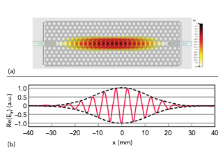
Figure 3 (a) The resonator structure and electric field intensity. (b) Gaussian envelope of the resonant mode’s electric field.
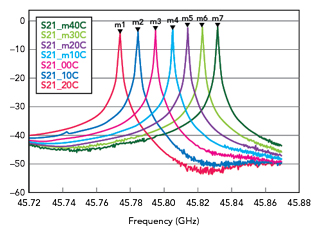
Figure 4 Measured resonator insertion loss at different temperatures.
The resonator insertion loss as a function of temperature is shown in Figure 4. The unloaded Q at room temperature is 115,000 and the resonance frequency is 45.77 GHz. The unloaded Q increases to 200,000 at -40°C upon cooling. Correspondingly, the insertion loss decreases to -3.6 dB at 40°C. Lowering the temperature below -10°C results in a relatively small increase in unloaded Q. This mirrors the temperature dependence of the HRS loss tangent.3
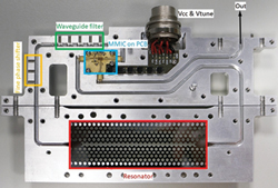
Figure 5 Final MMIC VCO assembly.
These results illustrate the low dielectric loss of the 1 mm thick neutron transmutation-doped HRS 6 in. wafers supplied by TopSil GlobalWafers A/S, along with the superior quality of the holes etched using the deep reactive-ion etching (DRIE) method carried out by V-Micro SAS. Maintaining hole sidewall angles very close to 90 degrees is key to achieving a high Q-factor. Due to the 1 mm thickness of the HRS wafers, maintaining straight sidewall angles across the thickness is a difficult task and requires significant DRIE process expertise.
OSCILLATOR TOPOLOGY
Figure 5 shows the topology and assembly of the feedback voltage-controlled oscillator (VCO). Both the active circuitry and the resonator reside in a split-block aluminum housing with WR-19 waveguides milled into the housing. The input and output of the MMIC circuit are connected by bond wires to microstrip lines that couple to the waveguide. A waveguide bandpass filter and fine and coarse phase shifters are also included. The EBG resonator connects to the WR-19 waveguides using HRS triangular tapers that protrude into the waveguide.

Figure 6 MMIC VCO circuit layout.
The active circuitry and the resonator can be tested individually. The two parts of the oscillator are joined by WR-19 flanges integrated into the housing. The total power consumption of the oscillator is 215 mW, its size is 157 × 88 × 29 mm and the weight is 442 g, including all connectors.
MMIC LAYOUT AND DESIGN
The active circuit MMIC is designed using the IHP Microelectronics 130 nm SiGe BiCMOS SG13S process. The MMIC layout is shown in Figure 6. The chip contains a two-stage loop amplifier consisting of a driver amplifier stage and a balanced power amplifier stage, a 10 dB coupler to couple a fraction of the oscillator power to the output, an electrical phase shifter and a coupling amplifier. The 10 dB coupler is realized by coupling transmission lines on the top two metal layers of the chip (TM1 and TM2). The coupling amplifier is realized as a standard common-emitter single-stage amplifier with 8 dB gain.
The loop amplifier uses a cascode design for the first and second stages. The loop amplifier shows good input and output matching as well as unconditional stability over the complete frequency and temperature range. The small-signal gain ranges from 19.1 dB at +20°C to 21.8 dB at -40°C. The small-signal results of the simulation are shown in Figure 7.

Figure 7 Simulated small-signal loop amplifier results. Input and output return loss (RL), Gain, Stability Factor k and Stability Measure (meas, right y-axis).
The electronic phase shifter consists of a 90-degree hybrid coupler terminated by varactor diodes at two ports, as shown in Figure 8. The simulated variation of transmission phase and insertion loss in response to varying the tuning voltage is displayed in Figure 9. The total simulated phase variation is 32 degrees. The insertion loss of more than 4.5 dB is rather high due to the varactor diode loss. Measurement on test chips of the structure showed a good match of the measured characteristics with the simulation results.
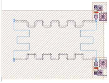
Figure 8 Electrical phase shifter chip layout.
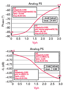
Figure 9 Simulated phase shifter phase and amplitude variation.
WAVEGUIDE FILTER AND MECHANICAL PHASE SHIFTERS
The waveguide filter and the mechanical phase shifters were characterized in a dedicated milled test structure consisting of a WR-19 waveguide. The circuits are shown in Figure 10 where the filter is the first structure on the left of the housing, circled in yellow. The fine phase shifter is in the middle, circled in green and the coarse phase shifter is the last structure on the right, circled in blue.
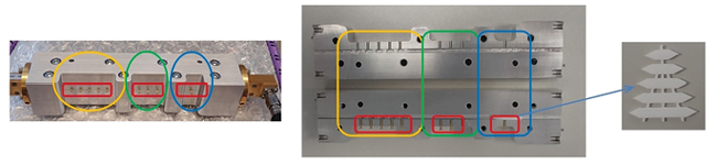
Figure 10 Side view of test structure and the coarse phase shifter Teflon pieces.
The waveguide filter serves to suppress the oscillation of other resonator or enclosure modes. The fifth-order filter was designed so that the center frequency can be varied between approximately 45.0 and 45.9 GHz with M1.4 polyether ether ketone (PEEK) screws. The measurement results of the filter from 44 to 46 GHz are shown in Figure 11(a). Figure 11(b) shows the passband in more detail and Figure 11(c) shows the wideband performance of the filter.
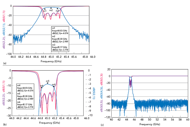
Figure 11 (a) Complete filter response. (b) Filter passband response. (c) Wideband response.
The tuning range of the electronic phase shifter is only 32 degrees. To augment this range, additional mechanical phase shifters were incorporated to ensure that the feedback loop can be adjusted for a multiple of 360 degrees total phase shift, ensuring oscillator startup. To achieve sufficient precision, two mechanical phase shifters were cascaded. For coarse adjustment, a WR-19 waveguide was partially filled with Teflon (permittivity = 2.1) to vary the electrical length. As shown in Figure 10, the Teflon pieces were tapered to improve impedance match. The length of these Teflon pieces varied from 16 to 36 mm in 2 mm steps. The measured phase shift between two adjacent lengths is approximately 60 degrees and the impact on insertion loss is less than 0.7 dB.
The fine phase shifter consists of three PEEK screws whose length within the waveguide can be varied. The measured phase difference between the minimum and maximum screw settings is 47 degrees. The measured tuning accuracy is better than 0.5 degrees. The change of the insertion loss is less than 0.2 dB within the total tuning range.
PHASE NOISE AND ELECTRONIC TUNING RANGE
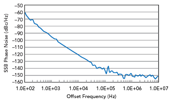
Figure 12 Measured oscillator SSB phase noise at -10°C.
An operating temperature of -10°C was chosen owing to the temperature dependence of the resonator quality factor. Figure 12 shows measured phase noise levels of -95, -120 and -143 dBc/Hz obtained at offset frequencies of 1000, 10,000 and 100,000 Hz, respectively. The oscillator output power is -1.2 dBm and the electrical tuning range of the oscillator is 239 kHz. For stable operation, the temperature stability needs to be better than 239 kHz/2.3 MHz/°C = 0.1°C.
CONCLUSION
This article describes the design and testing of a low noise mmWave oscillator employing an HRS resonator with a reduced dielectric filling factor. The authors believe that the phase noise values are the lowest published at this frequency range for electronic feedback oscillators without noise degeneration. The oscillator is lightweight with a small form factor and low power consumption. Future work will concentrate on improving the electronic frequency tunability to relax the requirements on temperature stability and to enhance the technology readiness level for space applications.
ACKNOWLEDGMENT
This work was funded by the European Space Agency (ESA-ESTEC) under the ESA Contract No. 4000130082/20/NL/HK.
References
- J. Chen, D. Kuylenstierna, S. E. Gunnarsson, Z. Simon He, T. Eriksson, T. Swahn and H. Zirath, “Influence of White LO Noise on Wideband Communication,” IEEE Transactions on Microwave Theory and Techniques, Vol. 66, No. 7, 2018.
- D. B. Leeson, “A Simple Model of Feedback Oscillator Noise Spectrum,” Proceedings of the IEEE, 54 (2): 329–330, doi:10.1109/PROC.1966.4682.
- J. Krupka, W. Karcz, P. Kaminski and L. Jensen, “Electrical Properties of As-grown and Proton-irradiated High Purity silicon,” Nuclear Instruments and Methods in Physics Research B 380, 2016, pp.76–83.
- W. J. Otter, S. M. Hanham, N. M. Ridler, G. Marino, N. Klein and S. Lucyszyn, “100 GHz Ultra-high Q-factor Photonic Crystal Resonators,” Sensors and Actuators A 217, 2014, 151–159.
- Y. Akahane, T. Asano, B.-S. Song and S. Noda, “High-Q Photonic Nanocavity in a Two-dimensional Photonic Crystal,” Nature, Vol. 425, October 2003.
- E. Lia, I. Ghosh, S. M. Hanham, B. Walter, F. Bavedila, M. Faucher, A. P. Gregory, L. Jensen, J. Buchholz, H. Fischer, U. Altmann and R. Follmann, “Novel mmWave Oscillator Based on an Electromagnetic Bandgap Resonator,” IEEE Microwave and Wireless Technology Letters, Vol. 33, No. 6, June 2023, pp. 863–866, doi: 10.1109/LMWT.2023.3268090.