
Modern RF transceivers represent more than just separated receiver and transmitter functionalities within the same box. In an operational scenario involving several transceivers, even a “perfect” receiver can demonstrate high-end performance only if the spectral purity of the transmit signals is sufficiently high. Therefore, a transceiver design must align major RF parameters and building blocks between transmit and receive paths to form a combined optimized transceiver architecture! In the following, a state-of-the-art “perfect” transceiver architecture is described.
When a receiver and transmitter are operated at different locations and far away from each other, the only relevant receive parameter is sensitivity, while the only relevant transmit parameter is output power. The closer a transmitter is to the receiver, the more significant are additional performance characteristics for both. While the receiver must increase its robustness to withstand the strong transmit signal at its front-end, the transmitter must increase its spectral purity to ensure that no spectral component from the transmit signal falls into an adjacent receive channel.
Overall system performance is determined by the minimum usable frequency offset between a transmit channel and a receive channel with a given decoupling between a receiver and a transmitter operating a given output power.
This so-called co-site situation directly influences the specifications, for example, adjacent channel power ratio for the radio communication equipment. Within a particular frequency band and its typical applications, the operating parameters may lead to a different transceiver architecture when compared to different applications in other frequency bands. Consequently, a transceiver for a 5G mobile phone base station, for example, may look completely different than a mobile phone base station designed to operate in the high frequency (HF), very high frequency (VHF) or ultra-high frequency (UHF) band.
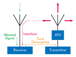
Figure 1 Co-location scenario for a transceiver.
While the best architecture for communication equipment in a particular frequency band may vary slightly, for simplicity we focus only on systems below 600 MHz.
DERIVATION OF KEY PARAMETERS FOR SPECIFICATIONS
The transceiver RF design is directly driven by some key parameters whose values and ranges strongly influence the required circuits and the concepts for major building blocks designed to meet system requirements. Therefore, it is highly recommended to define the worst-case system scenario concerning RF power levels and frequency offsets and derive the key parameters from this setup (see Figure 1).
It is reasonable to assume that such a system is built up by using several transceivers of the same type that are operated either in a receive or transmit mode. This allows system performance to be enhanced by optimizing the receive and transmit paths as parts of a common transceiver RF architecture.
SPECIFICATIONS FOR A HIGH-END TRANSCEIVER
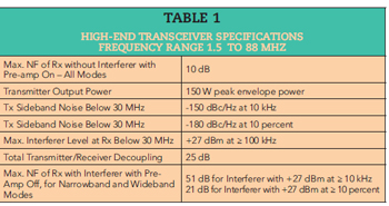
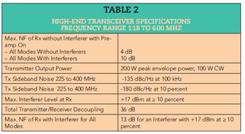
Table 2
The data in Tables 1 and 2 is based on the use of very robust input stages necessary to enable operation in a highly contested environment. These input stages use filters and amplifiers in a cascaded configuration where some elements can be bypassed. Consequently, the total receiver noise figure (NF) with all filters active is on the order of 10 dB, typically 4 to 6 dB higher than usually expected. In situations where no strong interferers are present, some co-site filters can be bypassed and additional high gain amplifiers can be activated, which leads to noise factors on the order of 4 dB or less.1
WHAT ABOUT RECEIVER INTERMODULATION?
The specifications in Tables 1 and 2 do not show values for receiver intermodulation because in a co-located environment, all interferers that may cause intermodulation products within receiver front-ends are those radiated from transmitters at the same station. These transmitted signals are present at any other transmitter antenna and create so-called backward intermodulation products, which are then reradiated into the station.
These spurious signals appear at the same frequencies where receiver intermodulation signals would appear as well. This means that even with no receiver intermodulation effects at all within a radio station, operation on a frequency affected by transmitter backward intermodulation is not possible.