
Local oscillators (LOs) are critical components in mmWave radar and communications systems. Dielectric resonator oscillators (DROs) are commonly used up to a maximum frequency near 30 GHz. Above that, the LO signal generation requires additional multiplier circuits and bandpass filters. These additional components can create adverse effects by increasing phase noise, circuit complexity, mass, power consumption and reducing reliability.
This article describes an mmWave oscillator using a high Q electromagnetic bandgap (EBG) resonator with a reduced dielectric filling factor. The measured results of the resonator demonstrate an unloaded room temperature Q-factor of 115,000 at 45 GHz. The active MMIC includes a two-stage loop amplifier, a coupler, an electronic phase shifter and an output amplifier. The oscillator has phase noise levels of -95, -120 and -143 dBc/Hz at offset frequencies of 1, 10 and 100 kHz, respectively. The authors believe these noise levels are the lowest reported values for electronic feedback oscillators without noise degeneration.
The LO is at the heart of any communications system or RF-sensing unit. Its frequency stability has a broad impact on achievable data rates or radar sensor sensitivity. Wideband communications now use bandwidths up to 1 GHz and higher-order QAM modulation to target data rates above 40 Gbps.1 For low bit error rates in these applications, the error vector magnitude (EVM) needs to be sufficiently small. EVM impairments primarily originate from the LO phase error and to a lesser degree from power amplifier compression, AM-to-PM conversion and Johnson noise. Consequently, the phase error obtained by integrating the LO single-sideband (SSB) phase noise needs to be sufficiently small. In this context, the relevant frequency limits for integration range from the digital receiver frequency tracking bandwidth, typically 100 Hz to several kHz, as the lower limit to one-half the signal bandwidth as the upper limit.
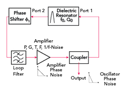
Figure 1 Oscillator with feedback topology.
For radar sensing applications, the echo, a Doppler-shifted radar pulse, is down-converted to baseband using the LO. A detectable signal needs to be larger than the LO phase noise at the relevant Doppler frequency. At 45 GHz, a target moving at 100 km/h creates a Doppler shift of 8.3 kHz. For 1000 km/h the offset frequency is 83.3 kHz. Therefore, the phase noise in the offset frequency range between 5 and 500 kHz should be minimized to maximize the radar sensitivity for relevant applications like space.
Generally, an oscillator consists of an active element, like an amplifier or Gunn diode and a resonator as the frequency-determining element. An electronic phase shifter is needed to adjust the feedback phase for constructive interference and enable phase stabilization as part of a PLL. This common feedback topology is depicted in Figure 1.
The phase noise of a free-running oscillator is governed by Leeson’s equation2 as shown in Equation 1:

where:
Ql is the loaded Q-factor of the resonator
α is the 1/f flicker noise corner frequency of the active element
G is the gain of the active element of the oscillator
F is (large signal) noise figure
P is the available power at the loop amplifier output
k the Boltzmann constant
f0 is the operating or carrier frequency
f is the phase noise offset frequency
T is the thermodynamic temperature.
At small offset frequencies, the phase noise increases quadratically with the operating frequency and decreases quadratically with the loaded Q-factor of the resonator used in the feedback loop. This increases the difficulty of building a low phase noise oscillator at mmWave frequencies. Traditionally, low phase noise quartz oscillators have been designed at lower frequencies, typically 100 MHz maximum and their output signal is subsequently multiplied to the target frequency. The drawback is this method increases the oscillator phase noise by 20 log (N) with N being the frequency multiplication factor. Moreover, low phase noise frequency multipliers consume a considerable amount of current.
For frequency generation directly at mmWave frequencies, DROs may use low loss ceramic materials such as BMT (Ba(Mg1/3Ta2/3)O3). This enables operation to around 30 GHz, but this material has a dielectric loss tangent of 2 × 10⁻⁴ at 45 GHz.3 For a dielectric loss-limited resonator, the Q-factor is the inverse of the dielectric loss tangent, meaning that BMT can achieve a maximum Q-factor of 5000 and this is not sufficient.
High resistivity silicon (HRS) is an interesting alternative with dielectric losses described by Equation 2:

where:
ρ is the electrical resistivity of the material.
ω is the angular frequency.
ε’ and ε’’ are the real and imaginary parts of the dielectric constant, respectively.
The electrical resistivity depends on the purity of the material and typically varies between 10 kΩ•cm and 50 kΩ•cm for standard HRS. Values up to 416 kΩ•cm have been achieved with proton or neutron irradiation or Au-doping. At 45 GHz, the corresponding values of the HRS loss tangent are 8.1×10⁻⁵ (ρ =50 kΩ•cm) and 2.0×10⁻⁵ (ρ = 416 kΩ•cm), which are far lower than the BMT loss tangent.
The temperature variation of the permittivity is another important consideration when choosing the resonator base material. BMT has been designed to minimize the temperature variation with a permittivity gradient of dε’/dT=5×10-6/°C at room temperature. However, HRS is not temperature compensated and the gradient of the permittivity is much larger, with a value of 1.2×10⁻³/°C at room temperature.3 The temperature gradient of the resonance frequency can be calculated from the temperature gradient of the material permittivity as shown in Equation 3:

This is 2.3 MHz/°C For HRS at 45 GHz.
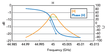
Figure 2 Resonator transmission magnitude and phase.
For the oscillator, the electronic phase shifter in the feedback path in Figure 1 can compensate for the temperature-induced resonator frequency variation. The resonator phase shift is 90 degrees across its 3 dB bandwidth, as shown in Figure 2. By adjusting the phase shifter by 90 degrees, the oscillator frequency can be adjusted by the amount of the 3 dB bandwidth. This is because the total oscillator open-loop phase is required to stay at a multiple of 360 degrees. As an example, for irradiated HRS, a Ql of 50,000 is expected. In this case, the 3 dB bandwidth at 45 GHz is only 900 kHz. Consequently, the electronic phase shifter can correct for temperature changes of approximately 0.4°C, which equates to 900 kHz/2.3 MHz/°C. This compares to a 3 dB bandwidth of 9 MHz and a frequency gradient of just -5 kHz/°C for BMT. This shows that temperature stabilization is not required for BMT.
RESONATOR DESIGN
EBG resonators are formed from resonance-supporting defects created within metamaterials engineered to have an EBG. The metamaterial’s EBG prohibits the propagation of electromagnetic (EM) waves in specific directions, allowing localization and confinement of a resonant defect mode. EBG metamaterials can be realized using periodic metal or dielectric structures and feature an EBG in one, two or three dimensions. This work considers a resonator made entirely from HRS with an engineered 2D EBG due to its ease of fabrication.
A common method for creating an EBG resonator is to construct a dielectric 2D EBG from a periodic lattice of air holes perforating a slab made from a high permittivity dielectric. The resonator is created by introducing a defect in the periodic lattice of air holes through the omission of several consecutive holes.4,5 In this case, the achievable resonator Q-factor values are essentially limited by the dielectric loss of the base material. Further enhancement of the resonator Q-factor can be achieved by reducing the fraction of the resonant EM energy confined inside the dielectric and storing a larger fraction in air. In this case, the Q-factor can be expressed as Q=1/(ρ∙tanδ) with tanδ being the loss tangent of the HRS substrate and ρ being the dielectric filling factor. The dielectric filling factor is defined as the fraction of the electric energy inside the silicon compared with the total stored electric energy of the resonant mode, as shown in Equation 4:

where:
Vsi is the volume of the silicon forming the EBG resonator
Vt is the total volume containing the resonant mode
E is the electric field of the resonant mode
ε’si is the dielectric constant of HRS
ε’(v) is the position-dependent permittivity.