MMWAVE TWTS
Many TWTs using helix circuit designs to generate hundreds of watts of power at Ka-Band for communications systems are available today. Suppliers include Stellant, CPI, Thales, Photonis, Teledyne and NEC. These TWTs can have efficiencies over 50 percent with output power densities around 100 mW/cm3.
For applications where size or weight are at a premium, mini-TWTs are often used. These devices have shorter circuits and reduced gain that is offset by higher-power solid-state drivers. Lower voltages allow for a very compact high-voltage power supply to be packaged with the TWT. At Ka-Band, up to 100 W is available with power densities of hundreds of mW/cm3. At E-Band frequencies there are fewer commercially available options, as shown in Figure 9.
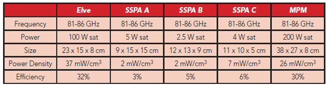
Figure 9 Comparison of E-Band amplifiers.
ELVE TWTAS
The construction of vacuum electronic devices, such as TWTs, is often an artisan process; it requires extremely high-precision machining and assembly. The tolerances become more exacting as the frequency increases. Each mmWave circuit is constructed and assembled individually and can take months to complete. Fabrication techniques for the circuit include micromachining (milling or EDM) as well as electroplating around LIGA molded photoresist, etched silicon or 3D-printed polymer structures.9,10,11,12 These processes do not easily accommodate design changes to individual circuits with minimal process adjustments. The processes used to date have significant limitations in the rate of production.
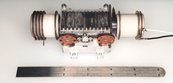
Figure 10 Elve E-Band TWT.
Elve has developed TWT design and fabrication techniques suitable for making mmWave TWTs in volume. The TWTs employ nanocomposite scandate tungsten emitters, which have a significantly lower work function than traditional TWT emitter materials. These special materials allow the emitted electron current density to be higher for the same temperature. As a result, a smaller emitter can be employed enabling the devices to be robust to minor dimensional errors in the beam-focusing structures while maintaining a long lifetime.
Elve TWTs use a “sheet” beam with an elliptical, rather than round, cross-section of the electron beam perpendicular to the direction of travel. The elliptical geometry reduces space charge density and power density in the beam, reducing the magnetic field requirements to confine the beam. Maintaining one of the ellipse dimensions small relative to wavelength enables good circuit efficiency, the ratio at which electron beam kinetic energy is converted into RF energy. The planar sheet beam configuration is well-suited for modern manufacturing techniques.

Figure 11 EPC powering the TWT heater, cathode and collectors.
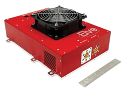
Figure 12 Elve E-Band PA including TWT and EPC.
Elve has developed an additive manufacturing technique to fabricate the circuits. Using this approach, circuits of different frequencies can easily be fabricated using the same process. Other devices that interact with electron beams, like klystrons or gyrotrons, can be made with this approach. The circuit technology is critical to Elve’s ability to rapidly iterate TWT designs. In production, it allows circuits and TWTs to be made quickly and consistently at volume. The compact planar design of an Elve TWT is shown in Figure 10.
Traditional microwave TWTs have demonstrated decades of reliable operation in space applications. Elve is designing and testing amplifiers to meet the same rigorous standards. The cathodes are the most sensitive portion of the TWT, so samples from each batch of powder are tested to verify the work function and emitted current. Elve is putting complete units through environmental testing including cathode heater cycling, operational on/off cycling, vibration testing and operation at temperature extremes to identify and resolve any potential reliability issues.
A complete TWT-based amplifier contains an electronic power conditioner (EPC) shown in Figure 11, which produces the operating voltages for the TWT. A compact TWT requires a negative cathode voltage of several kilovolts, typically in the range of -3 to -20 kV. The cathode voltage must be tightly regulated with extremely low ripple to enable ideal RF performance from the TWT. The cathode heater, floating at cathode potential, requires a few watts of power. The multi-stage depressed collector is biased with voltages between cathode potential and ground to enable efficient recovery of spent electron beam energy. In addition to generating the TWT electrode voltages, an EPC also provides the control logic and user interface to allow system integration.
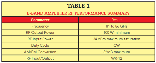
The Elve Vermillion E-Band amplifier shown in Figure 12 covers 81 to 86 GHz. The amplifier has a small signal gain of 20 dB, with other parameters shown in Table 1. Transfer curves are shown in Figure 13 with simulated linearity performance shown in Figure 14.
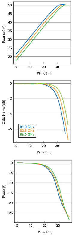
Figure 13 Simulated RF transfer characteristics.
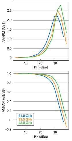
Figure 14 Simulated linearity characteristics.