
Major developments in science and technology, including software defined radio (SDR) systems, have come from original development for military purposes and then trickle down to civilian, telecommunication, and other applications. The development of RF and wireless devices has been an integral part of military research and push for the creation of state-of-the-art systems that provide fast, reliable, and secure methods of communicating and signal processing. For example, the evolution of digital systems greatly favored the development of modular, fast, and precise SDRs with high levels of flexibility and programmability, which explains why the military industry is shifting away from conventional analog RF systems to software-based solutions. Whether it be in mobile tactical radios carried by soldiers on the battlefield, RF systems in command & control (C2) posts, a radar on a fighter jet, a GPS-guided weapon controller, or satellite communication itself, SDRs are always involved.
In this article, we will discuss the technological requirements for the design, selection, and implementation of SDRs in the military industry, particularly regarding the radio front-end (RFE), processing power, and size, weight, and power (SWaP) specifications. For instance, SDRs designed for radar applications must provide support for chirps/pulses waveforms and automatic gain control, whereas tactical radio SDRs require advanced voice modulation/demodulation and fast video/data streaming capabilities. These specific requirements drastically affect the SWaP and performance specifications of the SDRs, so selecting the wrong device can certainly jeopardize the operation. Furthermore, the RFE requirements varies greatly from application to application, especially in terms of bandwidth, sensitivity, and number of channels. Here we will discuss several military applications, their RF requirements, and the impact on SWaP and cost.
SDR Basics
Before we discuss how SDRs can be applied in the military, let us review the architecture and design of these systems. As the name suggests, SDRs are radio transceivers that perform most of the RF-related operations in the software domain, implementing only the necessary analog hardware for antenna coupling, amplification, controlled attenuation, and filtering. They are divided into two main parts: the RFE and the digital backend. The RFE is responsible for all transmit (Tx) and receive (Rx) functionalities over a wide tuning range. This stage is critical for an SDR, as it defines several RF parameters, such as bandwidth, sensitivity, and multiple-input multiple-output (MIMO) capability. The highest-bandwidth SDRs contain RFEs with 3 GHz of instantaneous bandwidth over multiple independent channels with dedicated digital-to-analog convertors/analog-to-digital convertors (DAC/ADCs).
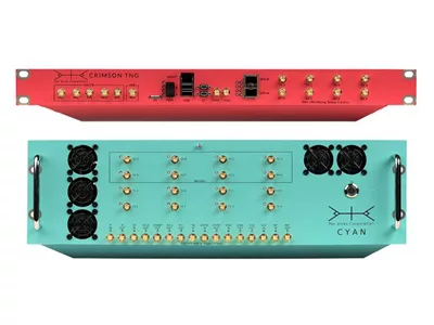
The digital backend is the brain of the SDR, performing essentially all the digital signal processing (DSP) functions inside a field programmable gate array (FPGA), including modulation/demodulation, up/down-converting, data packetization over Ethernet links (VITA49), and host interface. Connection to host systems is crucial in systems processing huge amounts of data (e.g., spectrum monitoring and 5G communication), so the highest-throughput SDRs in the market provide data backhaul using 4 x 100Gbps over qSFP+ transceivers, that can be linked to network interface cards of the host or other equipment. Some commercial off-the-shelf (COTS) SDRs are more self-contained, not relying on host systems but are usually limited in the performance they offer due to the self-contained limitations of the processing capabilities onboard. Besides the RFE and the digital backend, SDRs also require a time board to provide stable clock references for computation, synchronicity, and frequency determination; and a power board to properly distribute and manage energy to the whole system (see Figure 1).
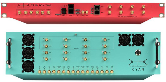
Figure 1. Examples of a high-performance SDRs from Per Vices, showing the Rx and Tx channels, and various ports (reference clocks, qSFP+, MGMT, GPIO, etc)
Although the general purpose and architecture of SDR transceivers are shared across devices, there are different types of SDRs of specific functionalities and performance limitations. RF Systems on Chip (RFSoC), for instance, were first developed by Xilinx and embed all radio functionalities inside a single chip, reducing the power consumption, elimination of board-to-board interfaces (for instance, the JESD204B interfaces between the backend and the RFE), and reduced the total latency, however, there is a limit in terms of performance for these systems including number of channels, RF performance, tuning range, and processing capability. SDRs with dedicated hardware, including RFE boards, timing boards, and power management boards, as peripherals to the digital backend, typically utilize an FPGA. These SDRs must implement interfaces between boards, including host connection and JESD204B serial communication, which increases latency and complexity, however, they significantly increase the versatility and flexibility of the design, providing a modular operation that can be tailored by the application requirements. These SDRs provide RFE boards with wideband tuning, very high RF bandwidth, and high-speed network capabilities. Most modular SDRs are COTS solutions, being ready for programming and implementation right out of the box, while RFSoCs sometimes require additional development resources for proper functionality.
SDRs in general are application agnostic, that is, they are suitable for any application requiring an RF to digital (and reverse) signal transceiver. Here, we focus on the military aspects of SDRs, and how their designs must comply with such rigorous requirements related to performance. In the following sections, we will discuss each of these components in the context of several military applications, including radar systems, RF communication devices, electronic warfare/signal intelligence (EW/SIGINT) equipment, and satellite communications (SATCOM) systems.
RFE Requirements
An RF front-end is a device or module that incorporates all the circuitry between the antenna and the digital backend in both the Rx and Tx signal chains, including impedance matching circuits, low-noise amplifiers (LNAs), RF amplifiers, mixers, variable attenuators, and DAC/ADCs. Among the Tx and Rx structures, it is worth mentioning the homodyne, the heterodyne (superheterodyne), and the modulated phase-locked loop (PLL). In the homodyne architecture, the I and Q signals are transposed directly from baseband to RF, reducing the total amount of components. On the other hand, the heterodyne, or superheterodyne, transpose the I and Q signals at an intermediate frequency (IF) and use mixers and local oscillators (LOs) to upconvert the IF signal to RF before transmission, which eliminates electromagenetic (EM) coupling between components. The modulated PLL applies a PLL to upconvert the IF signal, by using the frequency multiplication capabilities of PLLs, which reduces the phase noise, but at the cost of losing amplitude modulation information. Receivers are virtually all improved heterodyne circuits, including the Hartley, Weaver and IQ architectures, that improve image rejection, coupling and selectivity at the cost of more complexity and power consumption. RFEs need to operate under precise and stable clocks, for deterministic operation of mixers and proper synchronization between Tx/Rx channels, especially in MIMO applications.
Regardless of the Rx/Tx architecture, there are several performance figures of merit that define the RFE. Sensitivity and dynamic range, for instance, define the maximum and minimum RF signal amplitudes that the RFE can properly receive and how much the receiver output changes with a change in its input. These parameters greatly affect the applicability of the device, and are highly affected by the noise figure, saturation, and gain control. Linearity is also important for receiver performance, being quantified by the third-order intercept point (IIP3) figure of merit, which relates to third-order intermodulation distortion. In the frequency domain, the bandwidth describes the range of frequencies that the RFE can operate, which also limits its suitability for certain applications. The bandwidth of an RFE depends on filters, bandwidth of components, and ADC/DAC sampling rate. Other parameters include RF output power, which limits range, and LO step size.
Satellite communication, or SATCOM, is crucial in military missions, providing a reliable source of long-range communications, navigation, and spatial awareness. SDRs applied in SATCOM can either be designed for ground stations or space operation. Ground stations usually require high-performance and complex SDRs, with powerful RFEs capable of working with a wide tuning range of frequencies, to handle several different satellites; high sensitivity and dynamic range, as the high frequencies involved are prone to variable levels of attenuation that depends on the environment; and high time accuracy for proper uplink/downlink synchronization with different satellite constellations. Onboard RFEs, on the other hand, are designed for critical SWaP requirements, including only essential modules to save power and space.
Radars are the perfect devices for spatial recognition and target tracking, which are essential in military endeavors. They require powerful transmitters and sensitive and coherent receivers to properly operate, as any deviation in the received signal can contain important information about the target. The radar RFE must also provide high dynamic range, to address the variation of target distances, obstacles, and jamming. The RF transmitter must be designed to handle high RF power, as a lot of energy is necessary to sweep large areas although this can typically be augmented with the use of an external pre-amplifier and amplifier. Radar RFEs often require dedicated chassis for proper cooling and thermal management, with other requirements dependent on the specific type of radar application, which ranges from large ground stations to radars onboard small aircrafts. Modular SDRs are perfect for these systems, allowing easy replacement and improvement of the RFE to comply with the radar specifications. Finally, RFEs designed for phased-array radars must provide, besides basic MIMO capabilities, excellent timing definition, stability, and phase coherency between channels.
Computational/DSP Requirements
The digital backend is responsible for all the computation performed inside the SDR, which includes basic RF operations, such as (de)modulation and up/down-converting, host and RFE interface, and error correction algorithms. Digital filtering and mixing are some of the most basic DSP operations, which are used to limit the sidebands and convert the received/transmitted frequencies. COordinate Rotation DIgital Computer (CORDIC) mixing are digital structures used to multiply signals inside the FPGA using the CORDIC method, which are usually implemented in high-performance SDRs. Data packetization and encoding/decoding is also performed inside the FPGA, enabling host networking via VITA49 protocol with proper encryption. The FPGA is responsible for generating the waveform to be transmitted, while also handling the JESD204B communication link with the RFE convertors (ADCs and DACs). Application specific algorithms are also performed in the FPGA. For instance, in network applications, the backend act as a soft-modems for amplitude shift key, phase shift keying, and frequency shift keying modulations, as well as Digital Video Broadcasting – Satellite – Second Generation (DVB-S2); whereas for radar applications the backend performs clutter removal, automatic gain control, and matched filtering.
Reliable communication is essential in military endeavors, so the FPGA must also perform error correction algorithms, such as forward error correction using Hamming codes. Hamming codes are used to correct single-bit errors, and work by defining the number of parity bits, locating them in the codeword, and then use a parity check matrix to generate the syndrome. The number of parity bits is defined by the Hamming’s rule, which also determines the position of each bit (P is the number of parity bits, and n is the number of data bits):
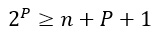
The syndrome points to the position of the bit error. For instance, Figure 2 shows the detection of transmission error in a 4-bit code. According to the Hamming’s rule, the minimum number of parity bits is 3, resulting in a 7-bit code. The parity bits are distributed in the positions corresponding to the power of two. The error can then be detected by using a look-up parity table, which generates a syndrome of [0 0 1]. The syndrome [0 0 1] indicates the bit corresponding to the first position is wrong, so the algorithm can just flip it to correct the word (notice that, in this example, the parity is even). If the syndrome was [0 0 0] no error is detected. The FPGA can easily perform this algorithm by using simple XORs and ANDs ports.
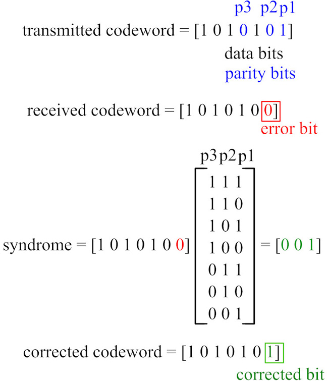
Figure 2. Hamming code used for Forward Error Correction
SDRs can either perform computations completely on the FPGA, which is the case of RFSoC devices, or perform post-processing computation on host systems and embedded CPUs. The first case is advantageous for very small self-contained systems performing simple operations, such as RF modules for tiny internet-of-things sensors. SDRs that enable high-speed data connection to external/host computers significantly expands their computational capabilities, while also providing easier configuration and integration to larger systems. Operations that require very low latency should be completely performed inside the FPGA, especially for parallel computation. Management and simple interfaces can be performed by a hard-processor unit in the backend, as latency is not so problematic in these operations.
For military SATCOM in the satellite payload, one is more likely to implement RFSoC device, especially when using very small nanosatellites in constellations. This is because they provide the fast computational power of the FPGA with suitable SWaP specifications, which is important for the implementation of DVB-S2/ DVB-RCS2 modems and fast error correction (Hamming codes and convolution codes). The digital backend in satellite applications must implement correction algorithms to address frequency shifting, propagation delay, and synchronization.
Tactical radios are the most basic RF components in the military, but even they vary greatly in terms of performance and SWaP. For instance, SDRs applied in large C2 units implements network interfacing for host communication, where post-processing and human-machine interfaces can be implemented, whereas handheld tactical radios for the battlefield must be self-contained and provide more embedded processing. SDRs for C2 often require communication over multiple modes, i.e., simultaneous Tx/Rx channels using different waveforms, frequencies and modems, however, both C2 and handheld SDRs must provide robust operation with interference/jamming protection algorithms, such as frequency hopping, to ensure communications in harsh environments.
Gaining territory is a fundamental principle in military operations, and it also extends to the radio-frequency domain. EW and SIGINT relate to the battles being fought in the RF environment itself, including spectrum monitoring, jamming, spoofing, and countermeasures. EW/SIGINT devices require host networking for post-processing and data storage, which means a lot of backhaul to transmit the huge amounts of data involved in wide instantaneous bandwidth capturing. The most suitable SDRs for this type of application typically have high-performance FPGAs and enable 4 x 40/100 Gbps Ethernet links over TCP/UDP for high-speed connection to external equipment and data storage solutions. Host connection is crucial to perform Fast Fourier transforms, power measurements, direction of arrival calculations, and other algorithms applied in SIGINT.
Radar applications require more specific computations, including anti-jamming and anti-cluttering algorithms. One example of anti-jamming algorithm is frequency hopping, which rapidly and periodically changes the frequency of the radar transmitter to avoid interception. Enemy forces may detect the signal and use it to deceive the radar or jam the receiver. Anti-cluttering refers to algorithms to reduce the radar sensitivity to unwanted echoes, including sea, trees, mountains, birds, and atmospheric turbulence, while focusing on real targets. Moving target indication is a popular example of anti-clutter detection that uses signal processing to filter out the stationary clutters, requiring a significant amount of FPGA and host computation. Radars using electronically scanned arrays require high levels of channel synchronization and parallel computation to handle multiple RF channels, so MIMO SDRs with excellent phase coherency are desirable.
SWaP requirements
Together with cost, SWaP requirements are application specific parameters that defines physical limitations to the SDR and affects both the analog and digital electronics involved, resulting in a major trade-off with performance. SWaP requirements can either refer to specific components, such as the RFE, antenna, and backend, or the whole system itself. This acronym is frequently used in the military industry, particularly because a lot of performance is expected from devices operating in remote and harsh environments, so SWaP specifications must be addressed in the early stages of the design. Basic trade-offs include performance versus power, performance versus size, and performance versus weight.
For satellite deployment in SATCOM applications, SWaP is critical due to the harsh conditions in space and the cost for launching payloads based on size and weight. Due to the obvious payload limitations, SDRs for SATCOM must be very small and light, which is very difficult in nanosatellite constellations. Telemetry, Tracking and Command devices based on the ISL72813SEH (driver circuit with integrated decoder from Renesas) can be made so small and efficient that onboard redundant systems are allowed. It is also important for power solutions for these SDRs to provide a type of automatic fault detection, isolation, and recovery, to avoid component damage due to faulty power sources, as physical intervention and maintenance are not practical in small satellites.
On the other end of the SATCOM link are the ground stations that send data to and from multiple satellites and the requirements for these systems are very different. For this element of the application, the most important performance requirements of SDRs are not related to SWaP but rather are based on tuning range, bandwidth, number of independent radio chains, and having the digital backhaul to pass the captured data to other systems. The SDRs used for ground stations are often the highest performing SDRs with 1 or 3 GHz of bandwidth, 4x 40G/100 Gbps digital backhaul, and a high number of channels.
Conclusion
RF devices are a fundamental part of military technology since the first radio units. They not only provide means for communication, recognition, navigation, and spatial awareness, but also compose the electromagnetic frontlines in electronic warfare and signals intelligence. With the fast evolution of digital technology, SDRs became the main RF transceiver for military RF applications, being applied in radars, SATCOM, tactical radios, and EW/SIGINT devices. When designing or selecting SDRs for military applications, one must address several requirements in terms of RFE, computational power, and SWaP, which means trade-off between performance and SWaP. For instance, large stations in fixed locations – such as SATCOM ground stations, C2 posts, land radars, and SIGINT stations - are much more relaxed in terms of SWaP, allowing them to perform several networking and communication functionalities with heavy signal processing. Mobile applications, on the other hand – including handheld devices, onboard radars, and satellite payload SDRs – are more limited and required specific solutions with less features. Addressing performance and SWaP requirements early in the design flow is crucial to meet the standards of the military industry.
Author Bio
Brendon McHugh is a field application engineer and technical writer at Per Vices and has a degree in theoretical and mathematical physics from the University of Toronto. Brendon is responsible for assisting current and prospective clients in configuring the right SDR solutions for their unique needs.