
Similarly, the flexible ground plane, which is separated from each of the microstrip ground planes by the dielectric, forms series-branching, low impedance parallel-plate transmission lines that are nominally a quarter-wavelength long at the operating frequency. This arrangement forms an electromagnetic bridge (EM-bridge) between the two sections of microstrip line. An EM-bridge can also be used to connect other forms of planar transmission line, such as stripline.
SIMPLIFIED EQUIVALENT CIRCUIT
Figure 4 shows a simplified equivalent circuit of the EM-bridge. The characteristic impedance of each series-branching line (series stub) is much less than that of the planar transmission line to maximize bandwidth. Each series-branching transmission line is terminated in an open circuit, which is transformed to a short circuit at each bridge abutment by means of the impedance inverter property of the quarter-wavelength line. Therefore, each short circuit (or very low impedance) allows the flexible trace and flexible ground plane to facilitate an EM bridging function between the adjacent sections of planar transmission line.
Since there is no metal-to-metal contact within the EM-bridge, this potential source of PIM is eliminated.
EM-BRIDGE SPACE APPLICATIONS
UHF Satcom
Large deployable parabolic reflector antennas are being considered for the payloads of the next generation of ultra-high frequency satellite communication (UHF satcom) systems, such as SKYNET 6. The EM-bridge technology enables deployable DRA antennas as an alternative means to form the required beam patterns. The Mathworks™ RF Toolbox™ enables a rapid analysis of the simplified equivalent circuit in Figure 4. Plots of |S11| and |S21| versus frequency are shown in Figures 5 and 6, respectively, for EM-bridges in the uplink and downlink antennas. The computed |S11| and |S21| values are less than ‐45 dB and ‐0.0025 dB in the 30 MHz frequency bands, which are centered at 255 and 305 MHz, respectively.
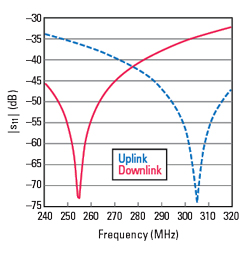
Figure 5 Computed |S11| of the UHF satcom EM-bridges.
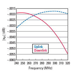
Figure 6 Computed |S21| of the UHF satcom EM-bridges.
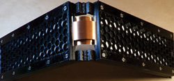
Figure 7 UHF satcom EM-bridge breadboard.
Figure 7 is a UHF satcom EM-bridge breadboard, a first iteration design as part of the BFN required for the downlink antenna. A honeycomb structure, produced by additive manufacture (3D printing), forms a superstrate carrier to support the trace in each of the respective microstrip sections, which are mechanically connected via 3D-printed hinges.
In this EM-bridge design, beryllium copper strips are used for the flexible trace and flexible ground plane. The metal strips are mechanically secured in the first half and are free to slide between sheets of PTFE (Teflon®) in the second half of the assembly. Sheets of PTFE are also used in the first half to ensure that there is no metal-to-metal contact, avoiding a source of PIM.
When the EM-bridge is in the folded state, the beryllium copper strips store mechanical strain energy, which provides an assistive torque to aid the deployment of the antenna panel. Several EM-bridges are integrated within each of the deployable antenna panels, thus forming a sprung “piano-hinge” arrangement.
Figures 8 and 9 show measured |S11| and |S21| versus frequency for the first iteration of the downlink UHF satcom EM-bridge breadboard. The measured results indicate that the lengths of the flexible conductors should be increased to optimize performance at the downlink band center frequency of 255 MHz. Although the analysis of the simplified equivalent circuit provides a quick assessment of the reflection and transmission characteristics of the EM-bridge, it excludes discontinuities at the transitions of the coaxial connector test ports and the effects of evanescent modes, which account for the differences between the computed and measured results. Nevertheless, even this first iteration greatly outperforms an alternative coaxial cable assembly, both electrically and mechanically.
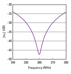
Figure 8 Measured |S11| of the UHF satcom downlink EM-bridge.
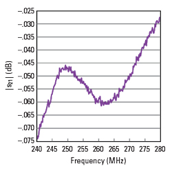
Figure 9 Measured |S21| of the UHF satcom downlink EM-bridge.
CubeSat Antennas
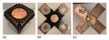
Figure 10 CubeSat deployable antenna breadboard, shown stowed (a), deployed viewing the patch antenna side (b) and back, showing the antenna feed network (c).
A CubeSat S-Band antenna typically uses a single microstrip patch radiating element mounted on the nadir-facing side to provide a circularly polarized radiation pattern for data link communication with ground stations. Figure 10 shows a breadboard CubeSat antenna that uses EM-bridges to deploy four panels by means of the mechanical strain energy stored in the folded regions of the ground plane and to feed the deployed linearly polarized microstrip patch radiating elements.