
A central phase-rotation BFN excites each of the radiating elements with the same amplitude, but with a phase difference of 90 degrees to produce a circularly polarized radiation pattern. This arrangement halves the S-Band transmitter power requirement, thus saving energy for use in on-board processing, or other mission needs.
COMSOL Multiphysics and the RF Module were used to design the BFN, the EM-bridges and the aperture-coupled microstrip patch radiating elements. Figures 11 and 12 show measured |S11| and |S21| versus frequency for the 2.45 GHz EM-bridge, demonstrating excellent performance.
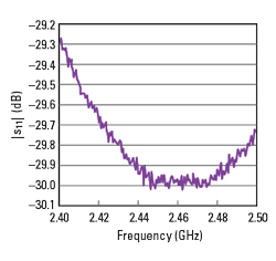
Figure 11 Measured |S11| of the 2.45 GHz CubeSat EM-bridge.
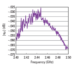
Figure 12 Measured |S21| of the 2.45 GHz CubeSat EM-bridge.
SENSITIVITY ANALYSIS
Finite element analysis simulations are performed on the following error sources: 1) variations in the permittivity of the dielectric medium separating and insulating the flexible trace from the microstrip trace, 2) the presence of a void between the dielectric medium separating and insulating the flexible trace from the microstrip trace, 3) lateral displacement of the flexible trace with respect to the microstrip trace and 4) angular displacement of the flexible trace with respect to the microstrip trace.
To investigate these sources, simulations are performed on an EM-bridge designed to encompass the entire global navigation satellite system (GNSS) frequency spectrum (∼1.1 to 1.7 GHz). The sensitivity simulations show that the presence of a void in the parallel-plate region of the EM-bridge has the greatest effect on S-parameters, i.e., return loss and insertion loss. Nevertheless, manageable manufacturing tolerances ensure the effect of the void is not an issue.
Simulations show that radiation from the EM-bridge is essentially the same magnitude as that from a reference length of microstrip transmission line, i.e., radiation from the EM-bridge is small compared with the radiation from the BFN.
TECHNOLOGY READINESS LEVEL
Validation of an EM-bridge to technology readiness level TRL5/6 was performed by the University of Southampton in the U.K., using the test facilities at the National Oceanography Centre. The vibration tests were performed on a Bruel & Kjaer medium-force shaker and thermal testing was performed in a Weiss Technik UK temperature test cabinet.
A test specimen of the EM-bridge was subjected to a thermal and vibration test campaign to the levels required by the European Space Agency for CubeSat operations. A total of six thermal cycles were performed along with nine vibration test runs, comprising two modal surveys and a random vibration test in each of the three orthogonal axes. Deployment functional testing was performed 5x throughout the test campaign, all of which were successful, confirming that the EM-bridge had survived all the test environments.
OTHER SPACE APPLICATIONS
Other space applications for the EM-bridge include synthetic aperture radar antennas, GNSS antennas, radio telescope antennas, deployable feeds for illuminating reflector antennas, deployable booms and mechanical beam steering through ±80 degrees (eliminating a heavy rotary joint).
TERRESTRIAL APPLICATIONS
Radio Astronomy
A proof-of-concept transportable/deployable radio telescope (TDRT) was designed, built and tested during the COVID lockdowns. The DRA antenna uses an array of 120 microstrip patch radiators to form a 2.5 × 2.1 m2 rectangular aperture in the deployed state. The H-plane linear arrays are fed by an E-plane feed network to give a Chebyshev weighting to the aperture excitation, which provides low sidelobes in the elevation plane to minimize the contribution of ground noise. A uniform aperture illumination in the azimuth plane maintains good efficiency.
The BFN uses an air substrate to eliminate dielectric loss and to reduce cost. The TDRT uses a stripline version of the EM-bridge, which has a measured insertion loss of 0.005 dB at the hydrogen line frequency of 1420.4 MHz, and thus it contributes < 1K to system noise.
In a traditional radio telescope, it is necessary to under-illuminate the parabolic reflector to reduce spill-over to the ground, which would otherwise increase the radio telescope’s system noise temperature. Under-illumination reduces efficiency and degrades angular resolution.
Due to the higher efficiency and better (2x) angular resolution of the TDRT, it outperforms a traditional 3 m diameter radio telescope. The 2.5 × 1.2 m2 flatpack form factor of the TDRT overcomes the transportation cost and handling difficulties associated with 3-m diameter dish antennas as well.
TDRT applications include outreach, university projects, teaching interferometry techniques and STEM activities for making transit observations of the sun, the galactic plane, Cygnus A and Cassiopeia A.
Curing of Composites
The current process of autoclave curing of carbon fiber composite parts in the aerospace, wind turbine and automotive industries is slow, energy intensive and expensive. Industrial closed-cavity microwave systems consume about 80 percent less energy than a comparable autoclave, with a 40 percent saving in cycle time. These systems, however, are susceptible to the generation of standing waves, causing hot and cold spots, which degrade the quality of the finished parts.8
The EM-bridge is an enabling technology in an agile robotic microwave system concept in which a lightweight robotic arm carries an antenna to apply microwave energy to the carbon fiber composite part. Artificial intelligence continuously interprets a thermal image of the composite part, identifying potential hot and cold spots and manages the deposition of energy to ensure that a uniform temperature distribution is maintained during curing the material.
SUMMARY
The EM-bridge is an enabling technology with the dual function of deploying antenna panels by means of stored mechanical strain energy and providing an extremely efficient transfer of EM energy across each inter-panel gap without recourse to metal-to-metal contact. Coaxial cables and related issues are eliminated from deployable structures. Passive intermodulation is minimized due to the absence of a metal-to-metal contact.
The technology readiness level has been validated to TRL5/6 for space applications, and to TRL7 in a TDRT. The EM-bridge is patented in 14 countries, with two other patents pending. There are opportunities for licensing, technology transfer and patent assignments.
ACKNOWLEDGMENT
The results presented are from a co-funded innovate U.K. project and activities performed through the Innovation Triangle Initiative and the Technology Transfer Program, funded by the European Space Agency.
- O. Heaviside, Improvements in Electrical Conductors, and in the Arrangement and Manner of Using Conductors for Telephonic and Telegraphic Purposes, U.K. Patent No. 1407, 1880.
- A. Thompson, J. Santiago-Prowald, P. Bensi and M. Aguirre, “A Stepped-Aperture Antenna Concept for Low Frequency SAR Missions,” Proceedings of the 30th ESA Antenna Workshop on Antennas for Earth Observation, Science, Telecommunication and Navigation Space Missions, May 2008.
- A. Thompson and M. S. Thompson, Deployable Panel Structure for an Array Antenna, U.S. Patent No. 8035573B2, 2011.
- A. Thompson and M. S. Thompson, Deployable Panel Structure, UK Patent No. GB2455311, 2012.
- M. Bayrak and F. A. Benson, “Intermodulation Products from Nonlinearities in Transmission Lines and Connectors at Microwave Frequencies,” Proceedings of the IEEE, Vol. 122, No. 4, April 1975, pp. 361–367.
- F. Arazm and F. A. Benson, “Nonlinearites in Metal Contacts at Microwave Frequencies,” IEEE Transactions on Electromagnetic Compatibility, Vol. EMC-22, No. 3, August 1980, pp. 142–149.
- A. Thompson and M. S. Thompson, Deployable Radio Frequency Transmission Line, U. K. Patent Grant GB2537885, 2017.
- B. Nuhiji, M. P. Bower, T. Swait, V. Phadnis, R. J. Day and R. J. Scaife, “Simulation of Carbon Fibre Composites in an Industrial Microwave,” Proceedings of the 12th International Conference on Composite Science and Technology, Vol. 34, Part 1, February 2020, pp. 82–92.
References