
Quartz-based oscillators are typically housed in an open cavity, ceramic package with the IC and quartz resonator bonded to the package substrate using two types of adhesives. Each quartz device is trimmed to the desired output frequency using either ablation or by depositing metal onto the quartz resonator. The adhesives and metal trimming can be a source of contamination that ages the resonator through mass loading and reduces reliability.
Shock and Vibration
Endura MEMS-based oscillators are more resistant to shock and vibration, in part because MEMS resonators have 1000× to 3000× lower mass than quartz resonators. The acceleration imposed on the MEMS structure from shock or vibration results in lower force than on the quartz crystal, which will induce a lower frequency shift. This is illustrated in Figure 4, which compares the phase noise of an Endura MEMS oscillator to several quartz temperature-compensated crystal oscillators (TCXOs). Subjected to random vibration with an RMS magnitude of 7.5 g over 10 Hz to 2 kHz, the MEMS oscillator has some 20 dB lower phase noise in this vibration frequency band. Integrating the phase noise over the vibration frequency band shows the undesirable integrated phase jitter (IPJ) of the MEMS oscillator increases by 1.2×, while the IPJ of the quartz TCXOs increased between 4.5× and 10× (see Table 1).
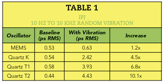
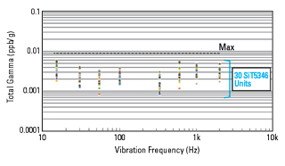
Figure 5 MEMS oscillator acceleration sensitivity with vibration from 15 Hz to 2 kHz.

Figure 6 DualMEMS oscillator architecture.
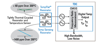
Figure 7 Temperature to digital converter.
Another measure of sensitivity to vibration is the frequency shift per g of applied sinusoidal acceleration, commonly termed the total acceleration sensitivity gamma vector and measured as ppb/g. Figure 5 shows the gamma vector over three axes of 30 Endura MEMS units subjected to vibration frequencies at eight frequencies between 15 Hz and 2 kHz. The maximum observed value is only 0.00577 ppb/g, the best performance in the industry.
Shock resistance is a key requirement for hypersonic weapons and another area where MEMS outperforms quartz. SiTime shock tests Endura MEMS products to 30,000 g, significantly higher than most quartz products can achieve. To put this into perspective, a 155 mm howitzer projectile experiences a peak acceleration of 15,500 g over a 9 ms pulse. Using typical system design margins of 1.5× the expected environment, components used with 155 mm projectiles should be certified for 23,250 g.
Temperature Sensitivity
Recent advances in MEMS technology, especially the DualMEMS® architecture (see Figure 6), provide benefits such as resilience to fast temperature ramps and low phase noise. The resonator and temperature sensor, shown on the left side of the block diagram, comprise the DualMEMS architecture. One resonator, the TempSense Resonator, serves as a temperature sensor, using its frequency versus temperature slope, and the other resonator, the TempFlat™ Resonator, provides a reference clock for the downstream PLL, designed to have a relatively flat frequency versus temperature slope. The ratio of frequencies between both resonators provides an extremely accurate measurement of resonator temperature, achieving 30 μK resolution. The tight thermal coupling between the resonators results from their proximity on the same die—within 100 μm—which achieves virtually no thermal gradient between the resonators.
In comparison, the temperature sensor in a quartz-based TCXO is integrated within an IC that sits below the quartz resonator on the substrate of the ceramic package. The spatial separation between the temperature sensor and the resonator enables a substantial thermal gradient between the two elements, introducing a frequency error when the oscillator is subjected to fast thermal transients.
A key element of the MEMS temperature compensation architecture is the temperature to digital converter (see Figure 7). This circuit generates an output frequency proportional to the ratio between the frequencies generated by the two resonators. It has 30 μK temperature resolution and up to 350 Hz bandwidth, enabling excellent close-to-carrier phase noise and Allan deviation (ADEV) performance.
ADEV is a time-domain measure of frequency stability. The advantage of ADEV over standard deviation is it converges for most noise types and is used for characterizing the frequency stability of precision oscillators such as TCXOs. Achieving good ADEV performance is critical for hypersonic weapons, as well as satellite communications and precision global navigation satellite systems.
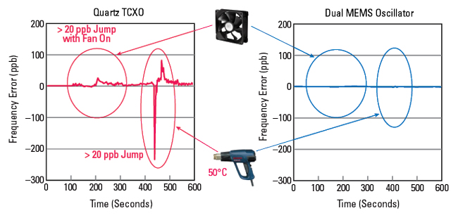
Figure 8 Frequency error of TCXO and DualMEMS oscillators following thermal shock.
Thermal Transients
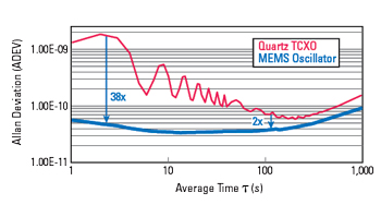
Figure 9 The Allan Deviation of the MEMS oscillator vs. quartz-based TCXO, both with airflow.
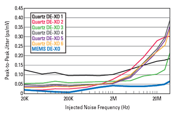
Figure 10 PSNR of MEMS vs. typical quartz-based oscillators.
The benefit of the DualMEMS architecture with fast thermal transients is shown in Figure 8. The thermal transients were created with a fan and heat gun applied to a DualMEMS oscillator and a ±50 ppb quartz-based TCXO. Following the application of heat, the quartz TCXO deviates 650 ppb peak-to-peak (from ‐450 to +200 ppb), exceeding its datasheet specification by 9×. The frequency change of the Endura DualMEMS oscillator is barely noticeable: 3 ppb or less, far below its specification of 100 ppb.
Rapid, turbulent airflow is a likely stress factor in hypersonic weapons and will cause die temperature changes, including fluctuations in heat flow from the oscillator to the environment. In extreme cases, this can cause vibration effects, which can be assessed from the ADEV. Figure 9 compares the ADEV of quartz-based TCXO and MEMS oscillators, both subjected to airflow. The Endura MEMS oscillator has between 2× and 38× better performance than the quartz TCXO over ADEV averaging times between 1 and 100 s.
Power Supply Noise Rejection
In addition to external stresses such as vibration and changes to ambient temperature and airflow, the typical system stresses will also be present in hypersonic weapons. These include power supply noise, which can produce crosstalk from nearby data lines and switching regulators. The oscillator must maintain low phase noise and jitter in the presence of such noise.
Power supply noise rejection (PSNR) is a measure of the resilience of the oscillator to power supply noise. It is defined as the ratio of the jitter at the output (in ps) divided by the amplitude of the injected sinusoidal jitter on the supply pin (in mV). Normally, sinusoidal jitter is injected onto the supply pin with 50 mV amplitude. Figure 10 shows the peak-to-peak jitter of a MEMS differential oscillator compared to quartz-based oscillators from six different suppliers. The injected power supply noise covers the frequency range from 20 kHz to 40 MHz. The low jitter demonstrated by the MEMS oscillator is achieved using multiple on-chip low-dropout regulators that isolate critical components, such as the voltage-controlled oscillator and the MEMS oscillator.
Summary
Hypersonic weapons have the potential to be among the most effective defense against adversaries due to their exceptionally high speed and maneuverability. Without careful design of the electronic subsystems, the harsh conditions caused by hypersonic speeds—very high temperature, rapid temperature change, extreme shock and vibration—can degrade if not destroy the components used in the weapon. For system timing and RF local oscillators, this article has demonstrated MEMS is superior to quartz-based oscillators and more capable of meeting the stringent performance and reliability requirements imposed by hypersonic environments.