
The unique capabilities of hypersonic flight present enormous challenges for timing system components, demands found nowhere else in a military’s inventory. This article describes these challenges and how MEMS oscillators are better suited than quartz-based solutions for meeting the requirements.
Quartz-based timing components have provided timing references for aerospace and defense applications for decades. While quartz-based oscillators have been enhanced to mitigate their shortcomings, they still have inherent disadvantages that challenge their performance in next-generation defense systems such as hypersonic weapons.
The development of timing devices based on MEMS can be traced to the need to overcome the shortcomings of quartz crystal oscillators for mission-critical applications. Today’s MEMS-based timing devices offer superior performance compared to quartz-based counterparts. MEMS is inherently reliable and rugged, making MEMS components well suited for the harsh operating environments encountered in aerospace and defense systems and, particularly, hypersonic weapons.
Hypersonic weapons pose unique challenges for the timing devices used in the mission computing, flight control, real-time signal processing and communications subsystems on the weapon. These challenges stem from the intimidating environment: extreme temperatures and pressures, vibration, shock and extremely high g-forces.
Hypersonic Weapons Explained
Hypersonic weapons are ultra-fast, low-flying, agile and highly maneuverable vehicles that are capable of avoiding detection and defense systems. Although ballistic missiles travel at hypersonic speeds above Mach 5, they have set trajectories and limited maneuverability. Hypersonic missiles travel at speeds between 3000 and 15,000 mph—1 to 5 miles per second—which is up to > 25× faster than a commercial jet aircraft. These characteristics of high speed, maneuverability and unusual altitudes make them challenging for the best missile defenses until the last minutes of flight, which is often too late.

Figure 1 The trajectories of hypersonic boost-glide vehicles vs. ballistic missiles. Source: Congressional Research Service, “Defense Primer: Hypersonic Boost-Glide Weapons.”
The two types of hypersonic weapons are hypersonic glide vehicles (HGVs) and hypersonic cruise missiles (HCMs). HGVs, also known as boost-glide vehicles, are typically launched from a ballistic missile, released at a specific altitude and speed and follow a flight path tailored to reach the target (see Figure 1). HGVs are not generally powered once released, although a small propulsion system may be used to accelerate arrival at the target and provide directional control.
In contrast, HCMs are powered by air-breathing scramjet engines after being launched from a rocket or jet aircraft. They fly at high altitudes, although lower than HGV altitudes. HCMs have the dual advantages of hypersonic speed and relatively low altitude, enabling them to hit targets within a 600-mile radius in just a few minutes. Although HCMs fly at lower altitudes than HGVs, their hypersonic speeds make them difficult to detect and defeat, well beyond what most current surface-to-air missile systems can reach.
The scramjet used in the HCM is essentially a jet engine that produces thrust by the combustion of fuel and an oxidizer, the latter obtained by consuming atmospheric oxygen. This propulsion technology differs from typical rockets, which carry both fuel and the oxidizer in separate tanks or as a form of solid fuel. Air-breathing limits scramjets to lower altitudes, where the oxygen content is sufficient to maintain combustion. Practically, the scramjet engine must first be launched and then begins operating after reaching a specific altitude.
Scramjets have been in development since the 1950s; however, they’ve been extremely difficult to perfect, with the most successful results produced only since the 2000s. Even though scramjets are conceptually simple, their challenges are immense, primarily because of the low altitudes where they operate. The atmosphere generates enormous drag, and at very high speeds the resulting high temperatures require use of exotic materials, so the engine does not burn up. Combustion in the scramjet creates another thermal challenge: reducing the airflow speed into the engine, from higher hypersonic to slower supersonic speeds, and burning fuel creates extreme heating of the engine and nozzle. The electronic components used in a scramjet weapon must withstand these extreme temperatures.
Both types of hypersonic weapons create severe operating environments: high temperatures, thermal shock, vibration and high g-forces that the electronic components—radomes, antennas, RF front-ends, digital processing and timing—must withstand while meeting specified performance. The remainder of this article focuses on the reference clocks used for timing and local oscillators, comparing the performance of MEMS and quartz technologies to the key environmental stressors imposed by hypersonic weapons.
MEMS vs. Quartz
SiTime® introduced the first MEMS oscillator in 2006 and has continued to improve MEMS timing technology, adding temperature compensation and phase-locked loops (PLL) to reduce jitter and phase noise, integrating voltage regulators to reduce noise and eliminating frequency jumps at certain temperatures. SiTime now offers Endura® ruggedized oscillators engineered for harsh environments such as those encountered in hypersonic applications.
MEMS timing devices are designed to be free of spurious mode crossings with the fundamental mode and of resonator-induced activity dips. The MEMS device uses a single mechanical structure of pure, single-crystal Si with a tensile strength of 7 GPa, about 14× higher than titanium’s 330 to 500 Mpa. During the manufacturing process, SiTime uses a proprietary encapsulation technique called EpiSeal® to clean the resonator and hermetically seal it, which effectively eliminates aging. This manufacturing technique underpins the exceptional reliability of MEMS oscillators, which achieve significantly better failure rates than those of quartz oscillators (see Figure 2). The mean time between failure (MTBF) of the Endura MEMS oscillator is 2.1 billion hours, approximately 50× greater than quartz-based oscillators.
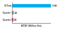
Figure 2 MTBF comparison of SiTime MEMS and quartz oscillators.
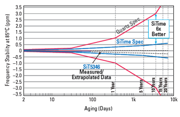
Figure 3 Aging specifications for MEMS and quartz-based oscillators.
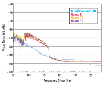
Figure 4 20 MHz oscillator phase noise with 10 Hz to 2 kHz random vibration.
With the hermetic EpiSeal process, contaminants are limited to low parts-per-billion (ppb), and an 1100°C anneal seals the Si crystal applied to the wafer in a high vacuum with extremely low or no impurities. The clean resonator cavity effectively eliminates resonator aging mechanisms (see Figure 3). The typical 10-year aging specification for a representative SiTime Endura MEMS oscillator is ±360 ppb versus ±3000 ppb for quartz-based oscillators.