
The Sivers TRXBF01 RFIC is integrated into a module with a 16-element Tx and 16-element Rx arrays that covers 14 GHz of bandwidth from 57 to 71 GHz. The Sivers module has a transmit power of +11 dBm per channel and a receive noise figure of 7 dB in a 90-degree horizontally scanned AESA. Figure 1 shows the front of the Sivers BFM01 module. These RFIC modules are supported by evaluation kits.
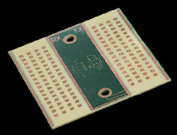
Figure 1 Antenna side of the Sivers Semiconductors transceiver.

Figure 2 RRI-100 research radar interferometer.
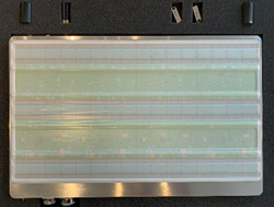
Figure 3 RRI-400 research radar interferometer.
A customized version with interfaces for coherent multi-module AESAs with wide bandwidth modulation has been developed specifically for aiRadar. This device, the BFM06012-RFM, has a modulation input with 4 GHz of transmit bandwidth, enabling 5 cm range resolution. The vertical beamwidth is modified with tapering to produce a 30-degree beamwidth with sidelobe levels below ‐20 dB. aiRadar has integrated these modules into research radars, the smaller RRI-100 is shown in Figure 2, the larger RRI-400 in Figure 3.
In both figures, the Tx/Rx row pairs are visible in the radome window recesses, with a pair at the top of the radome, a pair in the middle and a pair at the bottom. The spacing from top to middle is slightly different from the middle to bottom spacing. A double difference interferogram may be formed resulting in a virtual short baseline interferometer.
The aiRadar sensor electronics modules (SEMs) are configurable in frequency. A SEM can be mechanically modified to use a customized version of the Sivers Semiconductors BFM02801 for operation in the 24 GHz band, albeit with reduced bandwidth to comply with the frequency allocation. aiRadar and Sivers are currently evaluating a 77 to 81 GHz band TRM for migration from a research 66 GHz ADAS to an operational 77 to 81 GHz version.
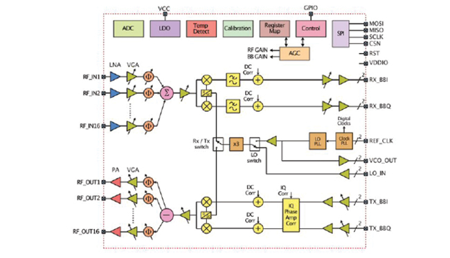
Figure 4 Transceiver RFIC architecture.
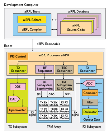
Figure 5 Software-defined radar block diagram.
Figure 4 shows the internal architecture of the Sivers TRM, and Figure 5 shows a functional block diagram of the radar. The digitized raw Rx outputs from the radar that appear in the radar data packets may be configured (in the RRI-400) as 16 digitized in-phase and 16 quadrature (I/Q) channels from each of the three azimuth Rx arrays, or a single digitally beamformed receive signal from each of the Rx arrays.
The 16 channels of Rx I/Q data provide the multi-aperture (16) SAR capability for 5 cm along track strip map imaging, the multi-baseline MTI capability using along track interferometry and the data for the DPCA micronavigation system.
The Sivers module provides zero IF Rx bandwidth to the aiRadar SEM with multiple control interfaces: a general purpose interface (GPIO), a serial programmable interface and a beamforming control interface. The aiRadar customized Sivers module has an external 22 GHz local oscillator (LO) interface with an internal 3× multiplier to the 4 GHz wide 66 GHz transmitter.
The Sivers RF LO interface, with a 1.33 GHz bandwidth at 22 GHz, and the Tx IQ interface are driven from the dual direct digital synthesizer (DDS) in the SEM, with modulation at two levels, on both the LO and the Tx IQ. This interface providers linear frequency modulated (FMCW) and arbitrary pulse modulation supporting LPI operations.
The high bandwidth arbitrary transmit signal is generated with a multistage RF lineup from the DDS in-phase and quadrature (I/Q) components, through a quad DAC with quadrature modulator correction and group delay correction enabling IQ compensation for gain, offset, phase and group delay between channels, a quadrature up-converter to 5.5 GHz and then a multi-channel multiplier to 22 GHz for distribution to the Sivers BFM devices.
Coherence, phase noise and Allen variance are critical in a radar at this frequency, particularly when used in a SAR mode. The primary reference is an ultra-low jitter oscillator. This reference is provided to an ultra-low noise clock jitter cleaner with dual-loop phased-locked loops to distribute the multiple coherent clocks to various subsystems.
SAR systems are typically deployed on larger drones or aircraft. SAR has been demonstrated by researchers on small drones (< 50 kg), but space varying errors due to aerodynamic turbulence and flight path position and attitude errors degrade resolution and are an obstacle to deployment on sUAVs. The aiRadar InSAR has an innovative solution to this, using the multi-aperture SAR capability, DPCA micronavigation, dual GNSS (GPS) receivers, nine-axis attitude sensors and time domain back projection to support unsupervised SAR processing.
COMMAND AND TELEMETRY; THE AiRPL ECOSYSTEM
The SEM is controlled by the aiRadar aiRPL, a compiled language with a syntax like C, which runs on the aiRPU. This language provides sophisticated multilevel looping and calls to the transmit pulse modulations, the beamforming and the receive data processing. This system is a powerful yet simple tool for the programming of radar configurations and almost arbitrarily complex operational modes.
The aiRPL ecosystem is composed of an integrated software development environment with compiler, databases, a command processor and a radar precision timing processing unit. The integrated software development environment consists of two main parts:
- The radar programming language—tools for the generation and sequencing of PRI bursts, sequences and frames.
Data structure creation and maintenance tools, including:
- Transmit Pulse Design
- Receive Configuration Design
- Beamforming Design
- TRM Hardware Configuration
- Radar Constraint Definition
- Image Quality Analysis
- Test and Maintenance.