
G-sensitive Components
It is important to identify an OCXO’s highest g-sensitivity components early in the design process to ensure they do not cause unacceptable phase noise degradation. The quartz crystal is generally the single largest source of g-sensitivity in a well-designed OCXO. However, other components such as transformers, inductors and capacitors can also exhibit significant g-sensitivity. Many RF cables, including ones rated to survive in high vibration environments, have significant g-sensitivities and should be vibrated separately to confirm their performance is adequate.
Since most components do not list g-sensitivity on their datasheets, sinusoidal vibration can be applied on a component-by-component basis to help identify g-sensitive components and resonances. This data can be used to choose alternative parts or to position sensitive components to leverage the techniques discussed below.
Magnetic Interference
Due to the frequency content of many vibration profiles specified in modern applications, electrodynamic shakers, which can shake up to at least 2 kHz, are often used to simulate real-world vibration environments. Unfortunately, unlike a typical real-world vibration environment, electrodynamic shakers also create strong magnetic fields (both AC and DC) capable of degrading the phase noise of high performance OCXOs. It is important to separate this phenomenon from vibration-induced phase noise, since the magnetic degradation will not correlate to actual field performance. One simple way to distinguish between the two effects is to suspend the unit under test (UUT) near its normal mounting point on the test fixture while running the vibration profile, so that the UUT experiences roughly the same magnetic field without being vibrated.
Any degradation seen in this configuration is likely caused by the AC magnetic interference (typically observed under 30 Hz). Magnetic interference can be mitigated by several approaches, including the use of magnetic shielding materials (such as mu-metal), active magnetic compensation or the use of a hydraulic shaker (which is typically limited to a bandwidth of up to 500 Hz).
TECHNIQUES FOR IMPROVING DYNAMIC PHASE NOISE
Passive Vibration Isolation
Passive vibration isolators are a common way of mitigating the vibration experienced by a system. They attenuate external vibration experienced by the OCXO above the resonant frequency of the isolation system, thus lowering the resulting dynamic phase noise. As mentioned above, this resonant frequency is determined by the payload mass and the stiffness of the shock mounts used. Passive isolation can be very effective in vibration environments with high frequency vibration, but care must be taken, as the environmental vibration will be significantly amplified around the resonant frequency. This can be seen in Figure 3.
This is often a worthwhile trade-off as attenuation increases every decade past the resonant frequency and many vibration profiles contain a significant portion of their power at higher frequencies. Passive isolation does significantly increase an OCXO’s dimensions as the system must accommodate vibration isolators, a payload and outer case, and sway space for the two to move independently of one another.
Vibration isolation can also cause thermal isolation since the payload cannot be easily heat sunk effectively to the chassis. Careful thermal management is required for military temperature environments (-40°C to +85°C) to prevent overheating of the payload. Finally, snubbers should be placed to prevent exceeding the shock mounts’ rated maximum displacement and should be sized to avoid damaging deceleration of the payload, particularly during shock acceleration events. When used properly, passive isolators can provide significant attenuation of high frequency vibration and prevent shock-induced damage to the OCXO.
Accelerometer-Based Vibration Compensation
Another way to improve an OCXO’s dynamic phase noise is by using accelerometer-based vibration compensation. This method employs an accelerometer to measure the vibration signal vector ![]() (f) experienced by the crystal and uses this information to generate a compensation signal C(f) to counteract the vibration-induced phase noise. C(f) is applied to the OCXO’s tuning line, modulating its frequency according to its tuning sensitivity (Hz/V) much like the vibration signal
(f) experienced by the crystal and uses this information to generate a compensation signal C(f) to counteract the vibration-induced phase noise. C(f) is applied to the OCXO’s tuning line, modulating its frequency according to its tuning sensitivity (Hz/V) much like the vibration signal ![]() (f) modulates the OCXO’s frequency according to the crystal’s g-sensitivity vector
(f) modulates the OCXO’s frequency according to the crystal’s g-sensitivity vector ![]() . The vibration data for each axis is scaled according to its calibration factor (determined through testing) and combined to create a C(f) whose frequency modulation is the additive inverse of
. The vibration data for each axis is scaled according to its calibration factor (determined through testing) and combined to create a C(f) whose frequency modulation is the additive inverse of ![]() (f)’s. In practice, the compensation system’s bandwidth is finite and can be limited by many factors including the accelerometer, the digital processing speed and the coupling between the accelerometer and the crystal. As the system’s bandwidth is approached the phase shift between
(f)’s. In practice, the compensation system’s bandwidth is finite and can be limited by many factors including the accelerometer, the digital processing speed and the coupling between the accelerometer and the crystal. As the system’s bandwidth is approached the phase shift between ![]() (f) and C(f) increases, resulting in the compensation system’s effectiveness diminishing over frequency.
(f) and C(f) increases, resulting in the compensation system’s effectiveness diminishing over frequency.

Figure 5 Effect of vibration compensation on Wenzel OCXO dynamic phase noise measured with Microchip Technology 53100A phase noise analyzer (Note: measured static phase noise limited by measurement setup).
The dynamic phase noise improvement obtained from applying accelerometer-based vibration compensation to a hard mounted 100 MHz OCXO subjected to an ASD of 0.02 g2/Hz from 8 Hz to 1 kHz is shown in Figure 5. The vibration compensation system achieves a Y-axis improvement of 30 dB or more from 40 to 160 Hz. The worst-axis phase noise is improved by 20 dB from 20 to 500 Hz. The compensation system’s effectiveness is reduced at higher frequencies but still achieves a phase noise improvement of over 13 dB at 1000 Hz. The OCXO’s compensated effective g-sensitivity ![]() calculated at 100 Hz is (1.8×10⁻¹¹/g, 8.84×10⁻¹²/g, 1.9×10⁻¹¹/g). The OCXO’s worst-axis RMS jitter in the frequency range of interest (10 Hz to 1 kHz) is reduced from 2×10-12 to 1.7×10⁻¹³ s.
calculated at 100 Hz is (1.8×10⁻¹¹/g, 8.84×10⁻¹²/g, 1.9×10⁻¹¹/g). The OCXO’s worst-axis RMS jitter in the frequency range of interest (10 Hz to 1 kHz) is reduced from 2×10-12 to 1.7×10⁻¹³ s.
Achieving the results described above requires careful selection of key components, chief among them the accelerometer itself. Important performance characteristics of the accelerometer include frequency bandwidth (discussed above), cross-axis sensitivity and g range. Excessive cross-axis sensitivity may limit performance across the entire frequency range if not accounted for by the compensation system. The accelerometer’s g range must be large enough to avoid saturation in the specified vibration environment.
Piezoelectric accelerometers provide a good combination of these characteristics, however as the bandwidths of MEMS capacitive accelerometers continue to improve, their inherent excellent temperature stability, small form factor and DC-coupled frequency response may prove more suitable for many applications. Low noise accelerometers of both technologies are available with signal-to-noise ratios that will neither limit compensation performance nor degrade the OCXO’s static phase noise. Some are offered in triaxial configurations, which are easier to incorporate into a design than three individual uniaxial accelerometers but may not be available with the required combination of performance characteristics.
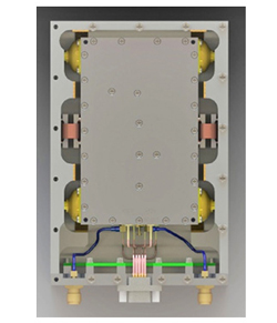
Figure 6 Vibration isolated and actively compensated OCXO.
Implementing the compensation system digitally allows for calibration to be done via software and even be automated to facilitate batch production. The digital architecture can be leveraged to provide additional functionality such as phase-locking to an external reference, frequency holdover and frequency aging correction. Additionally, many modern accelerometers only offer a digital interface such as SPI or I2C for communication, requiring the use of digital circuitry to decode their output. Furthermore, since a typical OCXO’s tuning sensitivity (Hz/V) is not constant over voltage, vibration compensation performance can be compromised if the phase-locked loop shifts the tuning voltage away from the point at which the unit was calibrated. While this effect can be minimized through careful tuning of the OCXO circuit, a digital system can eliminate it altogether by applying a correction factor derived through polynomial curve-fitting.
A potential drawback of using mixed-signal ICs such as ADCs and DACs is the introduction of additional sources of noise and bandwidth limitations. Noise mechanisms include noise voltage density, quantization noise and DAC glitch impulses. Attempting to filter this noise would result in degradation of the compensation signal C(f) and therefore lower compensation effectiveness. Consequently, it is necessary to prevent these sources of noise from being introduced into the circuit altogether.
Combining Passive Vibration Isolation and Accelerometer-Based Vibration Compensation
The two methods discussed above can be combined to provide synergistic benefits. An OCXO utilizing both techniques is shown in Figure 6. Accelerometer-based vibration compensation attenuates the effects of vibration on the OCXO’s dynamic phase noise at frequencies below its bandwidth. Conversely, passive vibration isolation is effective at reducing higher frequency vibration content, including frequencies above the compensation system’s bandwidth, but amplifies vibration near the resonant frequency (typically below 100 Hz) where active compensation is most effective. The combined effect of both dynamic phase noise mitigation approaches can significantly improve an OCXO’s performance, as shown in Figure 7.
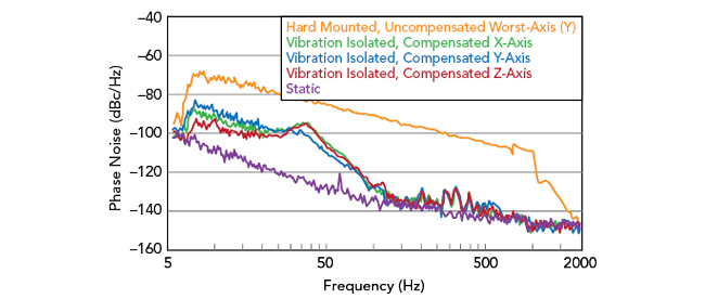
Figure 7 Combined effect of passive vibration isolation and active compensation on Wenzel OCXO dynamic phase noise measured with Microchip Technology 53100A phase noise analyzer (Note: measured static phase noise limited by measurement setup).
CONCLUSION
An accelerometer-based vibration compensation system achieved considerable dynamic phase noise improvement. The technology was successfully combined with passive vibration isolation. This active compensation technique complements the company’s existing Bootstrap active compensation technology.
Acknowledgments
The authors would like to thank Liz Ronchetti, Charles Wenzel, Mike Sawicki, Richard Koehler, Bryan Bousquet and Beth Huckabay for their support.
References
- J. R. Vig, “Introductions to Quartz Frequency Standards,” Army Research Laboratory, Fort Monmouth, 1992.
- J. R. Vig, “Quartz Crystal Resonators & Oscillators,” U.S. Army Electronics Technology and Devices, Fort Monmouth, 1987.
- Department of Defense, “MIL-STD-810H,” 2019.