
Oven-controlled crystal oscillators (OCXOs) provide highly stable, low aging and low noise frequency sources for applications in instrumentation, test equipment and telecommunications (including 5G) in the commercial, defense, military and space markets. When OCXOs are employed in high vibration environments, such as ships and aircraft, the resulting performance degradation must be considered. Improving an OCXO’s dynamic phase noise by lowering its acceleration sensitivity can help improve overall system performance in these applications.
In this article we present an accelerometer-based vibration compensation system that mitigates the effects of vibration on OCXO dynamic phase noise. We examine the use of this active compensation system as well as passive vibration isolation and discuss challenges and design considerations related to these techniques.
THEORETICAL BACKGROUND
Vibration and Dynamic Phase Noise
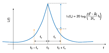
Figure 1 Spectral line pair induced by sinusoidal vibration.
An OCXO’s performance is largely dependent on the exciter’s quartz crystal, a piezoelectric resonator whose high Q factor enables the low phase noise characteristic of this type of oscillator.1 However, the dynamic phase noise exhibited by an OCXO in a high vibration environment often exceeds its static (resting) phase noise, limiting its performance. This is due to the fact that when mechanical force is applied to the crystal, such as when it experiences what is referred to as “proper acceleration” (as opposed to free fall, for example), the stress induced in the quartz lattice causes the oscillator’s frequency to change.2 The crystal’s acceleration sensitivity (or g-sensitivity) is a measure of how much its frequency changes in relation to the acceleration experienced by it. Since the quartz lattice structure is anisotropic, the crystal’s g-sensitivity is characterized by the vector ![]() (1/g). Applying an acceleration vector
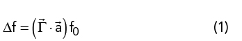
(1/g). Applying an acceleration vector ![]() (g) to a crystal of frequency f0 (Hz) results in a frequency change Δf (Hz) determined by the relationship
(g) to a crystal of frequency f0 (Hz) results in a frequency change Δf (Hz) determined by the relationship
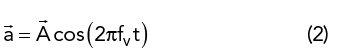
When the applied acceleration ![]() is a sinusoid characterized by a vibration frequency fv (Hz) and peak acceleration vector
is a sinusoid characterized by a vibration frequency fv (Hz) and peak acceleration vector ![]() (g)
(g)
the resulting vibration-induced frequency shift described in Equation 1 will vary over time. This type of frequency modulation creates spectral line pairs that are offset from the carrier frequency f0 at integer multiples of the vibration frequency fv. In practice, for many applications the corresponding modulation index is sufficiently low that only the first spectral line pair contains a measurable amount of power, as shown in Figure 1. In these cases, I1 (fv ) (dBc), the ratio of the power of this first spectral line pair to the power of the carrier, is
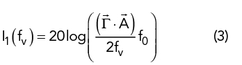
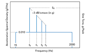
Figure 2 MIL-STD-810H Method 514.8, Annex D, Section 2.2, Category 13 – Propeller aircraft, Fig. 514.8D-2. Vibration environment characterized as sine-on-random vibration profile.3
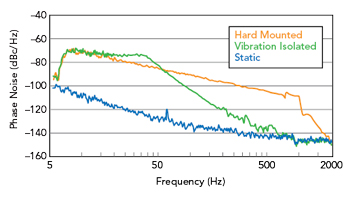
Figure 3 Effect of passive vibration isolation on Wenzel OCXO dynamic phase noise measured with Microchip Technology 53100A phase noise analyzer. (Note: measured static phase noise limited by measurement setup.)
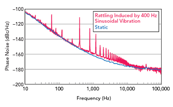
Figure 4 Rattling induced by 400 Hz sinusoidal vibration on Wenzel OCXO measured with Rohde & Schwarz FSWP signal analyze.
For example, a 100 MHz SC- cut crystal with a |![]() | of 3×10⁻¹⁰/g is vibrated with a 100 Hz, 2g single-amplitude sinusoid in the direction of its
| of 3×10⁻¹⁰/g is vibrated with a 100 Hz, 2g single-amplitude sinusoid in the direction of its ![]() will have its frequency shift within ±60 mHz of its nominal frequency (Equation 1). The corresponding spurious power ratio would be approximately -70 dBc (Equation 3). If the vibration frequency had instead been 1000 Hz the spurious power ratio would decrease by 20 dB to approximately -90 dBc. Finally, if instead the vibration were applied perpendicularly to the crystal’s
will have its frequency shift within ±60 mHz of its nominal frequency (Equation 1). The corresponding spurious power ratio would be approximately -70 dBc (Equation 3). If the vibration frequency had instead been 1000 Hz the spurious power ratio would decrease by 20 dB to approximately -90 dBc. Finally, if instead the vibration were applied perpendicularly to the crystal’s ![]() the oscillator’s frequency would be unaffected, and no spectral lines would be created.
the oscillator’s frequency would be unaffected, and no spectral lines would be created.
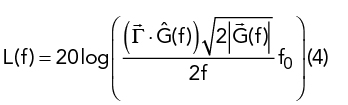
Real-world environments are usually not limited to exhibiting deterministic vibration in the form of discrete sinusoids. Instead, they exhibit random (non-deterministic) vibration which is characterized by using the statistical approach of power spectral density, specifically acceleration spectral density (ASD) specified in g2/Hz. Figure 2 shows an example “sine-on-random” vibration profile comprised of discrete sine tones overlaid on top of an ASD profile. The single sideband phase noise L(f) (dBc/Hz) caused by a vibration ASD profile ![]() (f) (g2/Hz) at a particular frequency offset from the carrier is
(f) (g2/Hz) at a particular frequency offset from the carrier is
For a flat ASD profile, induced phase noise will decrease by 20 dB per decade just as in the example provided for Equation 3. This can be observed in the hard mounted configuration performance shown in Figure 3.
Due to practical difficulties associated with effecting vibration in all three axes simultaneously, testing methodologies such as ones defined in MIL-STD-810H allow for dynamic performance to be assessed on a per axis basis.3 In applications that specify a vibration profile be applied to the OCXO, the resulting dynamic phase noise is used to evaluate performance. When the vibration profile is not yet known, the OCXO’s g-sensitivity can be presented instead, which can be calculated from phase noise data using Equations 3 or 4 for sinusoidal and random vibration, respectively.
Resonances and Rattling
Each part of a physical system has a natural frequency that is determined by its relevant mass and stiffness. If the relevant damping factor is low enough the system becomes resonant: amplifying the vibration experienced around the resonant frequency but attenuating it above the resonant frequency. The specific transfer function associated with each of these resonances is determined by the mechanical properties of the system and the affected area can range from a single component to the entire product.
Unintentional resonances caused by components, PCBs and chassis can create spectral lines, degrade dynamic phase noise and reduce reliability. It is often possible to move these resonances beyond the bandwidth of the vibration profile by staking components, adjusting chassis geometry and increasing the number of PCB mounting points. In environments with high acoustic levels, damping material may be necessary to reduce resonances in the kilohertz range.
Since resonances amplify vibration, they also cause displacement relative to non-affected parts of the system. Collisions occur when this relative displacement becomes too large for a given geometry and rattling can occur due to the repetitive nature of vibration. This can occur even between coupled objects if the force created by vibration exceeds the coupling force holding the objects together. Unlike resonances, rattling is a non-linear phenomenon that may only occur at higher vibration levels and causes abrupt force impulses. This phenomenon can manifest itself as spurious content harmonically related to the rattling frequency and/or as broader phase noise degradation, as seen in Figure 4. Consequently, one tell-tale sign of rattling is the presence of dynamic phase noise degradation outside the frequency range of the vibration profile.