

New demands in novel communications and radar systems require the adoption of active antenna systems to take them to new generations. High atmospheric attenuation along with higher degrees of channel fading conditions prevalent in upper microwave and mmWave frequencies have driven system designers across the industry to develop steerable, active systems, like phased array antennas. While existing phased array antenna systems may be suitable for their intended purpose, the addition of a synthetic gradient index (GRIN) lens, enabled by new dielectric 3D-printing techniques, simplifies the phased array system to increase steering performance and overcome the wide-angle limitations of flat panel phased array antennas.
STEERABLE ANTENNA SYSTEMS
For many high frequency RF applications, a fixed antenna array or an omnidirectional antenna is not sufficient to cover all required directions while providing sufficient radiated power to overcome atmospheric attenuation and high levels of channel fading. This has driven system designers to seek steerable systems to concentrate the signal for a specific target or user.1
While mechanically steerable antennas were developed to address this challenge for certain applications, they are less desirable for others due to limited steering speed for spatial multiplexing and limited reliability, since many consist of motors and other moving parts that are susceptible to wear.2
With recent advancements in flat panel electronically steered antennas, many high frequency applications can use antenna arrays that are electronically controlled by manipulating the signal feeds to individual antenna elements within a larger array. These are commonly manufactured using PCB fabrication processes that integrate the antenna arrays (e.g., patch antennas) with a feed network that connects them to other front-end components.
One way of achieving beam steering in these antenna arrays is to switch on and off certain elements; another way is to control the relative phase and amplitude of the signals to/from groups of array elements, or to/from each individual element. With a large enough antenna array and an electronic control and feed system, beam steering antenna arrays are designed to direct the main radiating lobe of the antenna array anywhere up to a maximum beam angle, rapidly steering the beam and even creating multiple lobes that are independently steered.3
The main disadvantage of flat panel electronically steered systems is the available effective aperture versus steering angle. This fundamentally limits the steering angle. Typically, for a flat panel phased array, the theoretical gain achievable at a given steering angle is a function of cos(θ), where θ is the target angle and θ = 0 degrees is the boresight direction.4 One possibility to overcome this limitation while preserving the many advantages of an electronically steered system is to supplement the system with a GRIN dielectric lens. A theoretical phased array lens system is imagined here.
DESIGN APPROACH
A phased array antenna system operating from 37 to 40 GHz is designed in Ansys HFSS for supplementing with a field-of-view enhancing GRIN lens. Assumptions are made to achieve a proof-of-concept and to ease the computational resources required to arrive at a useful design. A 16 x 4 element array is designed with rectangular patches at λ/2 spacing; and, for each individual patch, continuous phase and amplitude control is assumed. The array produces 23 to 24 dBi gain at boresight within the 37 to 40 GHz band with all elements excited (see Figure 1).
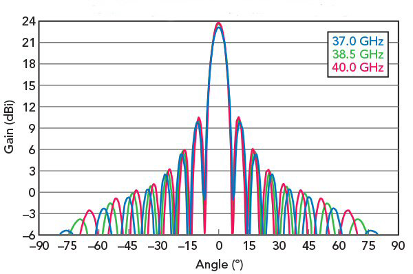
Figure 1 Simulated antenna pattern of the 16 x 4 element phased array without a lens and with uniform weighting.
A volume of 50 x 35 x 130 mm (height x depth x width) is chosen above the phased array as the potential area for a dielectric lens (see Figure 2). To efficiently iterate designs, an optimization technique is selected that maximizes performance for a given input figure-of-merit. In addition, to ease the computational load for optimization, the lens area is segmented into approximately 5 mm cubes—each representing a specific dielectric constant within the overall structure. The optimizing variables, include: 1) the Dk of each cube constrained between 1 and 3.6 in 0.2 increments and 2) the phase and amplitude settings for each element to achieve maximum directivity at ±90 degrees in azimuth, effectively achieving a 180-degree field-of-view in the simulated electronically steered, phased array antenna system.
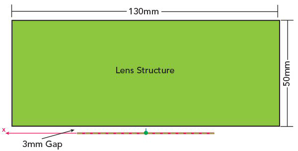
Figure 2 Lens design area above phased array antenna.
DESIGN RESULTS
The design includes three distinct high dielectric constant areas with graded lower dielectric constant areas (see Figure 3).
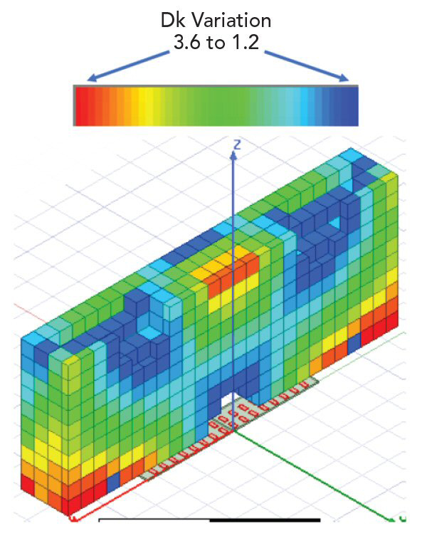
Figure 3 Isotropic view of GRIN lens system cut in half along symmetry plane.