
BEAM MEASUREMENTS
The AUT is mounted on a full spherical positioner and laser bore-sight aligned with the conductive surface (see Figure 2). The movement extents are set to beam scan AZ/EL ± 15 degrees in 0.5 degree steps. The required measurement dynamic range must accommodate the 15-degree beam width. To estimate the dynamic measurement range, the time domain can be used with a sufficient number of points. Figure 10 shows a dynamic range of almost 45 dB. Beam measurements (see Figure 11) are plotted for four test frequencies.

Figure 10 AUT time domain response.
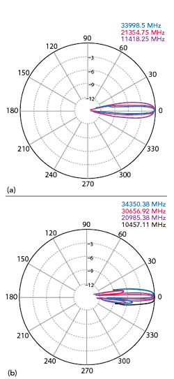
Figure 11 Elevation (a) and azimuth (b) beam measurements at several frequencies.
ACCURACY CONSIDERATIONS
The ratio of measurement wavelength to reflector size sets the lowest frequency that can be measured accurately. Careful inspection of Figure 6 shows that for frequencies below 1 GHz, the image gain is much higher than the 3-point gain. At 200 MHz the wavelength (59 in.) is larger than the 48-in. reflector. Inspection of Equation (7) reveals the possibility that as Γ becomes smaller, the source reflection dominates the calculation giving rise to a possible larger gain value depending on phase.
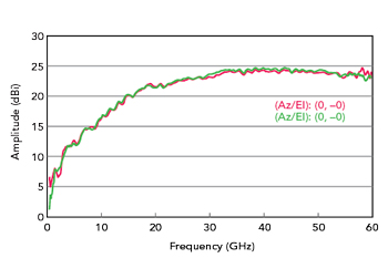
Figure 12 DE0540 horn antenna gain vs. frequency with a 48-in. reflector at 1 m (red) and 3 m (green).
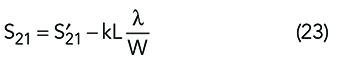
Figure 12 shows gain measured at 1 and 3 meters. A 5 dB gain error exists at 500 MHz. For a 48-in. square mirror this results in two wavelengths. As the frequency increases the error decreases to be negligible at about 2 GHz, and at 1 GHz the error is –1.2 dB. The vector ratio of the two traces represents the measurement error between 1 meter and 3 meters (see Figure 13). Ignoring edge diffraction, the forward S21 vector will add to the reflected S21 by a factor proportional to  where W is the width or height of the reflector and L is the path length. The relationship can be expressed as. That proportionality is expressed as
From Equation (22), the smaller  the less error is present. The constant, k, may be determined from a data set where it can be assumed L is small enough to ensure accuracy, 1 meter in this example. The corrected data then becomes
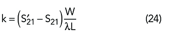
When Equation (23) is solved for k,
While a least squares algorithm would be most useful for the determination of k, a simple value can be determined by adjusting k until the lowest frequency S21 at 3 meters matches S21 at 1 meter. This is applied to data of Figure 13. Figures 14 and 15 plot the results with k = 3.8.
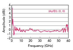
Figure 13 DE0540 horn antenna 1 and 3 m differential gain with a 48-in. reflector.
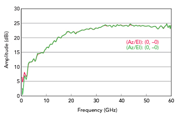
Figure 14 DE0540 horn antenna gain vs. frequency with a 48-in. reflector at 3 m (red) and with correction (green).
CONCLUSION
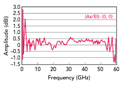
Figure 15 DE0540 horn antenna 1 and 3 m differential gain with a 48-in. reflector and correction.
The work of Purcell has been re-derived in vector form to take advantage of a modern VNA’s vector calibration capabilities. The resulting derivation is in good agreement with the classical 3-point method. The methodology enables antenna phase determination and a resulting S-parameter matrix. The matrix can then be used in system simulators to determine antenna bit rate error versus pointing angle. The reflection method has the advantage that only a single antenna is required; however, limitations determined by the wavelength to reflector ratio are not addressed here. The measurement is real-time, non-invasive and enables rapid antenna calibration with only a single port S11 measurement. It is shown that accurate measurements can be made down to two wavelengths (half the reflector width/height).
ACKNOWLEDGMENTS
The author wishes to express his thanks and appreciation to Diamond Engineering Inc. CEO James Matthew Martin and design engineer Joshua Taylor for their valuable support and contributions without which this effort would not have been possible.
References
- E. M. Purcell, A Method for Measuring the Absolute Gain of Microwave Antennas, Radiation Laboratory, Massachusetts Institute of Technology, Report No. 41-9, 1943.
- R. Q. Lee and M. F. Baddour, “Absolute Gain Measurement Method Under Mismatched Condition,” IEEE International AP-S Symposium, June 1987.
- T. G. Hickman and R. A. Heaton, “Measurement of Gain,” Microwave Antenna Measurements-NSI-MI, Scientific Atlanta, 1969, pp. 227-268, Web. www.nsi-mi.com/images/PDFs/Microwave_Antenna_Measurements.pdf.
- M. H. Hillbun, “Single Antenna Measurement using a Mirror and Time Domain,” IEEE Santa Clara Valley APS Chapter, July 2012.
- G E. Bodway, S-Parameter Circuit Analysis and Design, Application Note 95, Hewlett Packard, 1967.