
Radio astronomers have long been seeking to expand the capabilities of radar in their observations of the Solar System. In early 2019, efforts were initiated at the GBO GBT and the NRAO’s VLBA to accomplish this expansion. Following the collapse of the 300 m Arecibo Telescope in December 2020, the astronomy community raised questions about the future of some types of work conducted there, including the use of planetary radar systems for the observation of asteroids, inner- and outer-Solar System bodies and moons. The GBT and VLBA can expand on this work using an active radar system for planetary radar applications. Tests of this capability resulted in successful experimental efforts toward ground-based high-resolution imaging of nearby celestial bodies.
SYSTEM DESIGN
Selection of the GBT transmission frequency was interesting since NRAO discussions centered on Ka-Band. The experiment planned to use the VLBA as a receiver, but the array did not have a Ka-Band receiver like NRAO’s Very Large Array. Review of the VLBA receiving bands focused on the highest frequencies below Ka-Band possible. Analysis determined the best frequencies were from 13.75 to 14.0 GHz. The final license covered a 200 MHz bandwidth from 13.8 to 14.0 GHz.
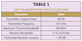
The transmitter was installed on the GBT at the prime focus (PF) position. It was developed to be compatible with existing GBT interfaces, and to be controlled and monitored remotely via a secure internet link. A duplexer allowed the transmitter and a pointing receiver to be connected to the same feed horn. The system was either in transmit or receive mode. Specifications for the transmitter and pointing receiver are listed in Table 1.
The GBO uses standard receiver housings for installation at the PF of all large antennas on site. For ease of installation and removal, the RI&S Ku-Band transmitter was built inside one of these PF housings (PFH). The housing consists of a rectangular box approximately 28 × 28 × 60 in.3 with brackets for hoisting and attaching to the mounting cage at the antenna focus. One 28 × 28 in. panel of the box carries the feed horn, while the opposite 28 × 28 in. panel carries connectors and fittings for the RF, electrical and cooling connections. The receiver mounting cage can be moved small distances in the X- and Y-directions parallel to the primary reflector, moved toward or away from the primary reflector to change receiver focus and rotated in both directions around the receiver axis.
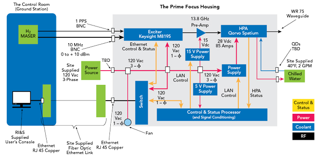
Figure 1 System block diagram.
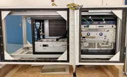
Figure 2 RI&S transmitter.
In November 2019, GBO shipped the PFH to RI&S for transmitter installation. The Peltier coolers were removed and replaced with a simple ethylene/glycol heat exchanger. The system block diagram is shown in Figure 1. The blocks in the light gray background were integrated into the PFH. Testing included verification of the gate biasing, power sequencing and pulse testing of the power supply into 5000 W loads. Mechanical members were water-jet-cut from aluminum slabs to ensure structural integrity, weight and balance. The payload needed to remain stable while being lifted and stowed into position atop the 500-ft. telescope. Pre-installation transmission tests occurred in GBO laboratories. The RI&S transmitter (see Figure 2) operated at full power into an RF load, which verified both the transmitter status and remote operations.
TRANSMITTER DEVELOPMENT
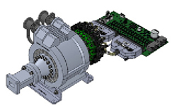
Figure 3 Spatium power amplifier.
The aggressive schedule and budget constraints mandated the use of commercial off-the-shelf hardware. RI&S conducted a detailed survey of high-power microwave amplifiers that included solid-state, TWTs, magnetrons, klystrons and cross field amplifiers. Size, weight, power and cost requirements and the need for continuous wave (CW) operation quickly narrowed the field. The Qorvo Spatium power amplifier was the only option that met these requirements. Graceful degradation, an integrated bias and sequencing, connectorized cooling jacket and simple 28 VDC power requirement in a compact volume made the Spatium the only choice (see Figure 3). The Spatium output power and VLBA sensitivity enabled the capability to generate spectacular lunar SAR images.
The Spatium amplifier is composed of an antipodal finline antenna array that is loaded into a coaxial waveguide to create a broadband multi-element combiner structure. The Spatium structure has demonstrated performance from 2 to 40 GHz and up to a decade of bandwidth in an individual amplifier. Qorvo has released a line of standard products based on the Spatium technology that is broken into three platforms covering typical radar, jammer and communications transmitter bands: 2 to 20 GHz, 8 to 16 GHz and 18 to 40 GHz. Each of the standard Spatium platforms allows for the combining of 16 solid-state amplifiers.
The Qorvo QPB1316 power amplifier uses the 8 to 16 GHz standard Spatium platform, combining 16 solid-state GaN MMIC amplifiers to achieve greater than 500 W of CW output power with a typical power-added efficiency of 27 percent. This high power amplifier (HPA) is compact with outline dimensions of 4.15 × 5.28 × 9.4 in., and with 3.35 × 6.89 in. for the associated bias control printed circuit board assembly (PCBA). Included in the dimensions is an integrated liquid-cooled clamp that allows the HPA to operate in both pulsed and CW modes while minimizing thermal resistance from the system cooling fluid to the GaN MMIC devices. The bias control PCBA requires a +28 VDC input and contains all required gate voltage and sequencing circuitry required for the GaN MMIC devices along with current monitoring for each of the 16 devices within the Spatium amplifier. The bias control PCBA is standard with Spatium products to ease integration at the next highest assembly transmitter.
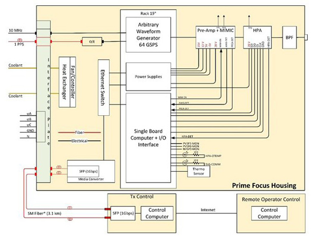
Figure 4 Transmitter block diagram.
TRANSMITTER INTEGRATION AND TEST
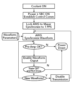
Figure 5 Transmitter operation.
Figure 4 is an overall block diagram of the transmitter identifying the GBT interfaces to include power, coolant, references, control communications and RF transmission. The control communications channel is a fiber channel to support a remote distance of 3.1 km between the local control node and the GBT. The operator control node is a remote internet node that was not originally planned but designed into the system to mitigate COVID-19 travel constraints.
Ultimately, the internet became the only way to operate the transmitter. The transmitters critical elements are the HPA driven by an arbitrary waveform generator (AWG) running at 64 giga samples per second with eight bits of precision. The AWG synthesizes the tones and the linear frequency modulated (LFM) waveforms at the center frequency of 13.9 GHz without up-conversion to reduce hardware and additional impairments. The pre-amplifier is enabled to drive the HPA with the synthesized waveform and the state vector is constantly monitored until a new waveform is required, or the test is terminated, by disabling transmission and shutting down gracefully. The flow diagram is depicted in Figure 5.