

The simplest quarter-wavelength, multi-port power divider, known as a Wilkinson divider,1-2 provides a match at all ports, low loss, in-phase power splitting and high isolation between output ports. Historically, this device was reported earlier.3-7 It was also described5 together with the so-called Gysel-type combiner,8 based on a conventional hybrid ring (rat race) proposed by Tyrrel.9 In this approach, the characteristic impedances of all lines in a conventional hybrid ring are equal such that Z1 = √2Z0, where Z0 is the characteristic impedance of all input and output lines of the circuits shown in Figure 1 .
Because of their reciprocity, these circuits may also be used to divide the power of one source (oscillator or amplifier). It has been shown5 that in this case, the isolating (ballast) resistor RB = Z0 can be represented by two equal resistors of double value 2RB, separated by a half-wavelength transmission line. The load line impedance Z0 and resistor RL(2) could be considered the result of the parallel connection of two lines with impedances 2Z0, each loaded by matching resistors 2RL(2), with the transmission lines connected to ports 3' and 3". This circuit can be considered the result of interconnecting two identical sub-circuits at the nodes a and b. This property will be used later on to form N-way combiners/dividers.
The symmetric hybrid ring has the same matching and isolation performance at ports 1, 2 and 3 as the conventional one, but broader bandwidth, as well as identical frequency characteristics at ports 1 and 2. That is because the circuit has a mirror symmetry axis (U-U) with respect to ports 1 and 2. The simplest quarter-wavelength two-way combiner has the same kind of symmetry1,3,4,5 in which the isolating resistor R = 2RB = 2Z0 can be represented as two series connected resistors Z0. The value of the characteristic impedance Z2 of one half-wavelength line does not affect the parameters of the combiner/divider at the center frequency. This impedance can be optimized (Z2 Z1) for broader bandwidth. Other methods have also been proposed to extend the bandwidth of hybrid rings.10-11

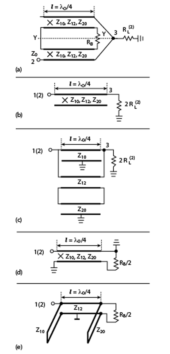
In the circuits shown, the ports 1, 2 and 3, with their two quarter-wavelength connected lines, form identical in-phase power transfer paths. The other parts of these circuits are different, but they provide the same function - isolation between ports 1 and 2 by using unbalanced isolating resistor(s) in the conventional and symmetric rings or balanced (floating) resistor(s) in the Wilkinson hybrid. The sub-circuits shown in Figure 2 are equivalent to each other at the center frequency with respect to their ports 1 and 25 and it can be easily verified by applying open-short conditions at ports 1 and 2. This equivalence provides a direct conversion from the conventional hybrid ring to both "Wilkinson- and Gysel-type" circuits, and is also used to form N-way combiners/dividers. The value of the characteristic impedance Z2 does not affect this equivalence and can be optimized to increase the bandwidth, as was previously acknowledged.
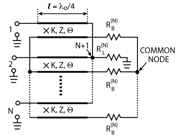
For expansion to an N-way combiner with circular (rotating) symmetry, any number (N>2) of sub-circuits can be connected to nodes a and b of axis Y-Y, as shown in Figure 3 .5 This type of combiner has been fabricated using a high power coaxial line operating in the VHF band. A similar construction with high power coaxial lines, but with a different design of the isolating resistors, was later proposed by Aves.12 The characteristic impedances Z1, Z2, Z3 can usually be different and are not equal to RB(N), while ZB = RB(N). The impedance Z0(N) of the output transmission line connected to the common input-output (I/O) port at node a and equal to the load impedance RL(N) = 2RL(2)/N can remain the same for any N (typically Z0 = 50  ) by increasing the characteristic impedances Z1 of the N quarter-wavelength lines between individual ports 1 to N and the common I/O port at node a. This causes a narrowed operating bandwidth, due to the increasing transformation ratio of those quarter-wavelength transformers.
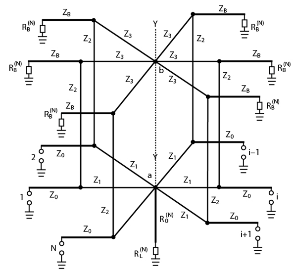
To provide full matching at ports 1 to N and theoretically infinite isolation between any two 1 to N ports at the center frequency, the following equations must be valid for any RL(N)
For ideal matching
For ideal isolation
For one particular case when RL(N) = Z0 and RB(N) = 2Z0, it follows from Equations 1 and 2 that Z1 = Z0√N and Z2 = √2Z0. For the second case, when RL(N) = Z0 and RB(N) = Z0, Z1 stays the same but Z2 = Z0. As a result, the so-called Gysel-type combiner8 has been derived directly from the hybrid ring. For any load resistance RL(N) with a load line having an impedance Z0(N), by analogy with the symmetric hybrid ring, the N-way combiner can be considered as the parallel connection of N lines with characteristic impedances NxZ0(N), terminated by load resistors NxRL(N).
For both particular cases considered, the value of the characteristic impedance Z3 may be equal to Z2 or can be optimized to improve the bandwidth. It was also shown in London5 that an N-way combiner1 is the result of interconnecting N sub-circuits ("halves" of the symmetrical hybrid ring for which N=2). Historically, other N-way in-phase, quarter-wavelength combiners been developed by joining any number N of 90° two-branch-line couplers.
During the past 35 years, several different circuit configurations of in-phase, quarter-wavelength dividers/combiners have been developed. They have specific connection lines (type, impedance, length), quantity of outputs/inputs and stages. These modifications provide wide bandwidth and arbitrary power division ratios, and are briefly summarized in Table 1 .
|
Table 1 | ||
|
Parameters |
Simplest In-phase |
Modified Dividers/Combiners |
|
Bandwidth |
narrow |
wide14,19,22,23,25 |
|
Power |
low |
high3-8 |
|
Power ratio |
equal |
unequal3 |
|
Type of transmission lines |
regular |
irregular or coupled19,22,24 |
|
Type of isolating resistor |
for max isolation |
for specified isolation15 |
Coupled-line Divider/Combiner
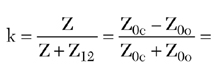
Consider the new, simple, in-phase, coupled-line divider/combiner shown in Figure 4 , where, in contrast with the hybrid rings, the isolating resistor is connected through the coupled lines and is DC isolated from the in-phase transfer path. For even-mode operation (in-phase, equal-amplitude excitations at ports 1 and 2), the equivalent circuits are the result of an open-circuit at the line of symmetry U-U. The equivalent circuit represents the interconnection of three fractional lines with a self impedance Z10 (conductor 1 - ground plane), a self impedance Z20 (conductor 2 - ground plane) and a mutual impedance Z12 (between conductors 1 and 2). All three lines are assumed to have identical electrical lengths Q, and form quarter-wavelength impedance transformers. Considering the simplest case of symmetrical coupled lines (Z10 = Z20 = Z), the resulting characteristic impedance of the quarter-wavelength transformer is
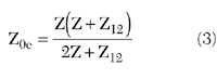
This transformer plays the same role as each line with impedance Z1 in the in-phase power combiner ring transformer path. Because only the value Z0e is specified for in-phase impedance transformation between RL(2) and Z0 at ports 1 and 2
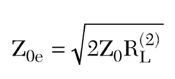
there exists some freedom in choosing the fractional impedances Z and Z12. This freedom can be used for optimizing the odd-mode decomposition circuit to provide maximum isolation between ports 1 and 2.
Consider, for example, the simplest case when the load impedance at port 3 is equal to RL(2) = Z0/2, for which the even-mode impedance Z0e = Z0 provides full matching, independent of frequency ( 0e = 0). The odd-mode impedance Z0o should be optimized to provide the minimum odd-mode reflection coefficient ( 0o ). It can be obtained by analysis of the odd-mode equivalent circuit.
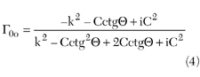
where
voltage coupling coefficient between the coupled lines
C = 1-k2
 = 2
= 2 l/
l/ 0 = electrical length of coupled lines
0 = guide wavelength at the center frequency
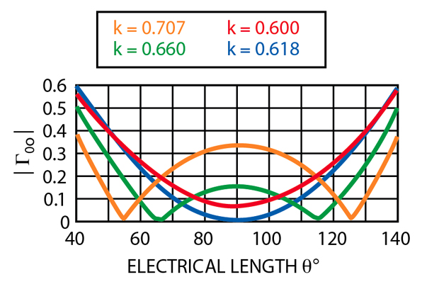
Some results of this calculation are shown in Figure 5 . Because of 0e = 0, the reflection coefficient at ports 1 and 2 is equal to 0o/2.
The isolation between ports 1 and 2 is defined as
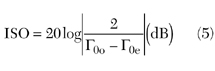
Table 2 illustrates some results of the numerical optimization of the two-way coupled line power combiner circuit for different bandwidth ratios Fmax/Fmin.
|
Table 2 | ||||
|
Fmax/Fmin |
1.5 |
2.0 |
2.5 |
3.0 |
|
Z ( |
81.46 |
82.50 |
83.59 |
84.70 |
|
Z12 ( |
48.0 |
44.4 |
40.8 |
37.3 |
|
k |
0.629 |
0.650 |
0.672 |
0.694 |
|
ISO (dB) |
34 |
24 |
20 |
17 |
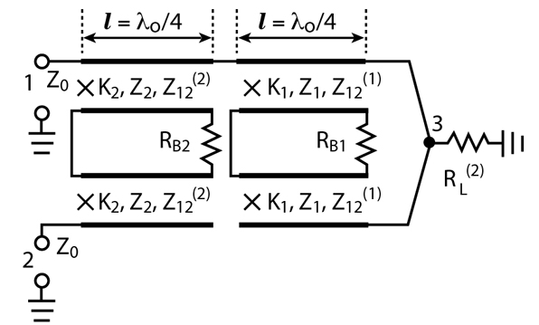
Significantly broader bandwidth of this type of coupled-line combiner is achieved in two or more stage devices. A schematic of a two-way, two-stage coupled-line power combiner is shown in Figure 6 . Consider the practical case when RL(2) = RB1 = RB2 = Z0 = 50 ( 0e 0). The results of the numerical optimization, using GENESYS v. 8.1 software (Eagleware Corp.), are shown in Table 3 . Typical characteristics are illustrated in Figure 7 for Fmax/Fmin = 2.33.
|
Table 3 | ||||||||
|
F max /F min |
Z 1 ( |
Z 12 ( |
k 1 |
Z 2 ( |
Z 12 ( |
k 2 |
| |
ISO |
|
1.50 |
146.87 |
45.3 |
0.74 |
83.85 |
126.6 |
0.398 |
0.018 |
56 |
|
2.00 |
145.47 |
42.6 |
0.773 |
86.97 |
117.1 |
0.426 |
0.050 |
42 |
|
2.33 |
144.30 |
40.6 |
0.780 |
88.94 |
112.4 |
0.442 |
0.074 |
36 |
|
2.50 |
143.88 |
39.3 |
0.786 |
90.28 |
108.2 |
0.455 |
0.086 |
34 |
|
3.00 |
142.61 |
36.1 |
0.798 |
93.56 |
99.23 |
0.485 |
0.118 |
30 |
N-way Coupled-Line Combiner
A two-way power combiner can be considered the result of a specific interconnection of two identical 90° directional couplers and can also be extended to an N-way in-phase combiner/divider, as shown in Figure 8 . In this case, N identical 90° directional couplers are interconnected in the same manner. The resulting circuit has the same circular symmetry as the N-way in-phase circuit, or the "Wilkinson-type" combiner and, in this case, there is an additional freedom - N identical coupled lines can be chosen as symmetrical or non-symmetrical. For the particular case of symmetrical coupled lines (Z10 = Z20 = Z), Equation 3 is valid. If the load resistance is RL(N) = Z0/N, Equation 4 is also valid.

In the common case, Equation 5 can be extended to any N, and the isolation between any two ports 1 to N is equal to:
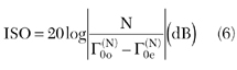
The values of 0o(N) and 0e(N) must be defined for proper N. For the case considered above, when RL(N) = Z0/N, 0e(N) = 0 and 0o(N) = 0o from Equation 4. Equation 6 is the result of the same circular symmetry as for the N-way in-phase circuit and can be used for any values of 0e and 0o, depending on the chosen ratio RL(N)/Z0.
Power Combiner with Specified Isolation
In some applications, a specified value of isolation is required. For example, for combining the power of oscillators in the in-phase Wilkinson circuit, a specified isolation provides mutual synchronization of the oscillators.15-18
This combiner with a specified isolation between ports 1 and 2 can be realized, as shown in Figure 9 . In this circuit, the value of the isolation resistor is R 2Z0, and the coupling between ports 1 and 2 becomes dependent on the value of RB. The influence of the resistance RB (with Y1 = 1/√2) on the parameters may be found from reference15
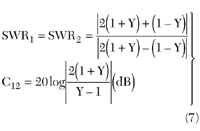
where Y = 2Z0/R is twice the normalized admittance of the isolating resistor R.
The input return loss at port 3 and the insertion loss are independent of R. Theoretical and experimental characteristics of the isolation C12 and match SWR1 = SWR2 versus the admittance deviation DU/U are shown.
In the circuit with the specified isolation and ideal matching of port 3, ports 1 and 2 are mismatched. For the normal functioning of oscillators, a good match at ports 1 and 2 is required. Calculations have shown15 that for a perfect match of ports 1 and 2 for a specified isolation, it is necessary that Y1 = 1/√2Y, that is Z1 = 2Z0√Z0/R. The same approach is valid for N-way combiners.
Some Design Approaches
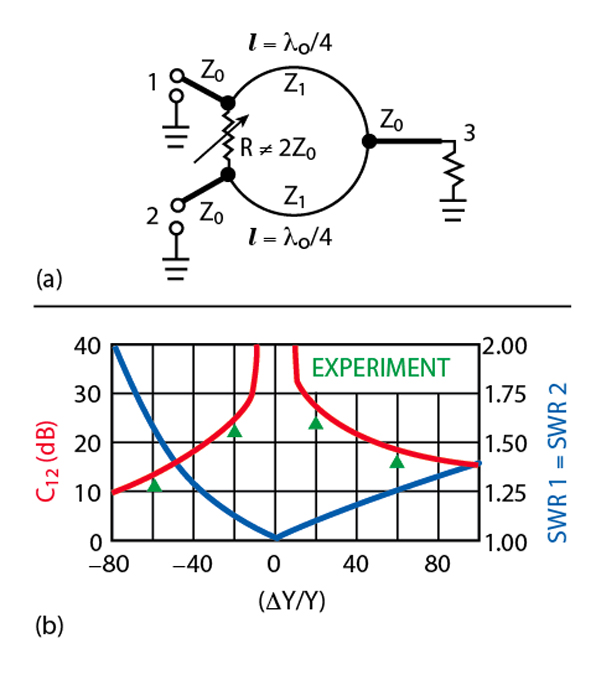
Conventional N-way power divider/combiners (Figure 10 )1-7 using coupled-line power combiners are difficult to realize in a planar structure when N>2, as the resistors need to be connected to a floating common node. The N-way planar circuits are subject to signal crossover and cross coupling, which adversely affects the isolation and mismatch characteristics. Also, such a crossover configuration limits the power-handling capability of the combiner. The size of conventional N-way dividers/combiners increases drastically as the number of outputs/inputs increases.

To overcome these limits, a multi-layer design can be used. Figure 11 represents a multi-layer, three-dimensional design. The input connections of the quarter-wavelength transmission lines and floating common node are realized with vias in the multi-layer construction. The two microstrip dividers are connected through a common ground plane to form a four-way combiner. The input 5 is connected to a stripline, and the outputs 1, 2, 3 and 4 are connected to microstrip lines. A multi-layer, six-way divider is also shown with all stripline input/outputs and with similar connections between layers by vias. This multi-layer, three-dimensional design is considerably more compact than a traditional planar design.
Conclusion
It was shown that widely used N-way combiners/dividers with the same property of circular symmetry can be derived from well-known simple devices and there is correlation between them. A novel coupled-line divider/combiner and a combiner with specified isolation are added to this family. The reduced size design approach considered for the simplest type of N-way divider/combiner could be extended to different types.
References
1. E.J. Wilkinson, "An N-way Hybrid Power Divider," IRE Transactions on Microwave Theory and Techniques , Vol. 8, No. 8, August 1960, pp. 116-118.
2. E.J. Wilkinson, "Power Divider," US Patent, No. 3,091,743, Cl. 333-9, 1963.
3. Z.I. Model and V.M. Katushkina, "Hybrid Combiners of High Power VHF Transmitters," Proceedings of Leningrad Politechnic Institute , Radiophysics, Vol. 194, 1958.
4. V.M. Katushkina and Z.I. Model, "N-way Power Combiners of VHF-UHF Transmitters," Electrosvaz , Vol. 7, No. 7, July 1959, pp. 17-25.
5. S.Y. London, "Independent Operation of High Power VHF Amplifiers on Common Load," Problems of Radio-Electronics ser. X, Technique of Communication , V. 6, 1959, pp. 87-96.
6. S.Y. London, "An N-way Power Combiner," USSR Patent, Cl. 21a4 901, No. 132674, 1960, Patents Publication Bulletin No. 10, 1960.
7. V.M. Katushkina and Z.I. Model, "Power Combiner of VHF-UHF Transmitters," USSR Patent, Cl. 21a4 901, No. 142346 (Priority April, 1957) Publication Bulletin No. 21, 1961.
8. U.H. Gysel, "A New N-way Power Divider/Combiner Suitable for High Power Applications," IEEE MTT-S International Symposium Digest , 1975, pp. 116-118.
9. W.A. Tyrrel, "Hybrid Circuit for Microwaves," Proceeding of the IRE , No. 11, 1947.
10. J. Hamed, et al., "Comparison of the Broadband Performance of In-phase Power Dividers and 0°/180° Directional Couplers," Microwave and Optical Technology Letters , Vol. 22, No. 9, September 1999, pp. 292-298.
11. S. March, "A Wide Band Stripline Hybrid Ring," IEEE Transactions on Microwave Theory and Techniques , Vol. 16, No. 6, June 1968, p. 361.
12. D. Aves, et al., "N-way RF Power Combiner/Divider," US Patent, No. 5,880,648, 1999.
13. L.I. Parad and R.L. Moynihan, "A Split-tee Power Divider," IEEE Transactions on Microwave Theory and Techniques , Vol. 13, No. 1, January 1965, pp. 91-95.
14. S.B. Cohn, "A Class of Broadband Three-port TEM-mode Hybrids," IEEE Transactions on Microwave Theory and Techniques , Vol. 16, No. 2, February 1968, pp. 110-116.
15. L.G. Maloratsky, "Microminiaturization of Microwave Elements and Devices," Soviet Radio, Moscow, 1976.
16. S.Y. London, "A New Broadband Coupled-line N-Way Power Combiner/Splitter," Applied Microwave & Wireless , May 2001, pp. 28-38.
17. L.G. Maloratsky, "Analysis of a Six-pole Ring-type Power Divider," Telecommunications Radio Engineering , Vol. 27, No. 9, September 1972, pp. 100-104.
18. L.G. Maloratsky, "The Basics of Print Reciprocal Dividers/Combiners," Microwave Journal , Vol. 43, No. 9, September 2000, pp. 108-124.
19. S.Y. London, "Broadband Coupled-line Power Combiner/Divider," US Patents, Int. Cl. H01P 5/12, No. 6,121,853, 2000 and No. 6,472,950, 2002.
20. A. Shor, "Broadbanding Techniques for TEM N-way Power Dividers," IEEE MTT-S International Symposium Digest , 1988, pp. 657-659.
21. K.M. Mussener, "Bruckenschaltung mit Lastausgleichswiderstanden," Earopaisches Patentanmeldung, Int. Cl. H03H007/48, No. 0 344 458, A1, 1989.
22. G. Linckelmann, "Shaltung zum Aufteilen oder Zusammenfuhren von Hochfrequenzleistung," Deutsches Patentamp, DE 27 33 888 C2, Int. Cl. H03H007/48, 1983.
Leo G. Maloratsky received his MSEE degree from the Moscow Aviation Institute and his PhD degree from the Moscow Institute of Communication in 1962 and 1967, respectively. Since 1962, he has been involved in the research, development and production of microwave integrated circuits at the Electrotechnical Institute and once served as an assistant professor at the Moscow Institute of Radioelectronics. From 1992 to 1997, he was a staff engineer at Allied Signal, responsible for the design of microwave devices. In 1997, he joined Rockwell Collins, where he works in RF and microwave integrated circuits for avionics systems. He may be contacted via e-mail at lgmalora@rockwellcollins.com.
Simon Y. London received his PhD degree in 1990 from the Electrotechnical Institute of St. Petersburg, Russia. He is a senior RF engineer with Advanced Power Technologies Inc., Washington, DC, and is currently involved in the design of high power broadband RF systems. Prior to joining APTI, he worked on the theory and design of broadband high power HF-UHF amplifiers, multi-port combiners/dividers, impedance transformers, matching units and filters. He may be contacted via e-mail at simon@apti.com.