
The term "one size fits all" has never applied to microwave test fixtures. They are instead almost always custom creations designed to serve a specific test application, and cannot easily be modified to meet other needs in the future. This has always presented a problem for cost-conscious designers. In research or design environments, tests required to verify the performance of a circuit sometimes need to be conducted only once, which makes it too expensive to have a custom test fixture built, either in-house or by a vendor. What the microwave designer has long needed is a way to build his or her own test fixture with parts that can be reused later for different projects. To satisfy this need the TFC-Series of R&D test fixture components has been created, the first of its kind to let designers take a "mix-and-match" approach to create test fixtures faster, and at a fraction of the cost of custom designs. To get designers started implementing fixtures in this manner, a $995 starter kit has been introduced that includes all the basic components needed to begin testing immediately, including two transitions that alone are each normally priced at $843.
The CMT-Series transitions, accompanying components and calibration kits allow a designer to quickly and inexpensively build a test fixture that is highly precise, and can be calibrated out of the measurement for extremely high accuracy in measuring the device under test (DUT). While not intended to replace a custom test fixture optimized for high volume throughput or some other customer-specified parameter, the TFC-Series nevertheless provides an excellent way to test small quantities of circuits. This tailors it for use in research and prototype areas of the design environment, in which small numbers of devices are usually tested.
The company's ability to maintain high precision even when the customer is building the actual fixture stems from its 18 years of experience in fixture design and manufacturing of microwave test components to extremely narrow tolerances for both manual and highly automated test beds. Once the basic concept of working with the TFC-Series is understood, building the fixture is vastly easier (and less time-consuming and less expensive) than producing one "in-house" from scratch using even the most sophisticated machining equipment.
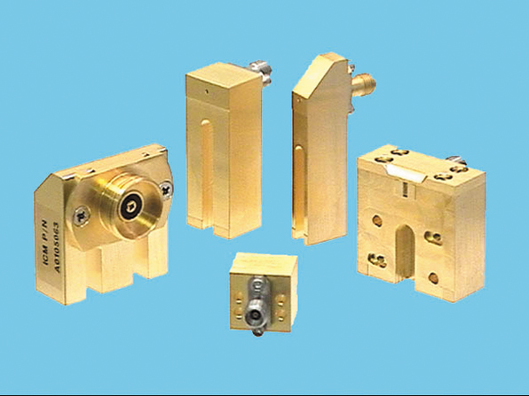
The centerpiece of the TFC-Series is a family of bolt-on coax-to-microstrip transitions, as shown in Figure 1 , which act as the interface between the coax connectors and the microstrip line. The company offers a wide variety of transitions, in wide-body and narrow-body styles, which cover every likely frequency and temperature range, configuration and microstrip line width. The wide-body version has two mounting slots for attaching the transition to the test fixture, and is designed for use with ICM's midsection adapters for testing packaged transistors. The narrow-body transition provides a single mounting slot and much narrower body for placing multiple transitions near each other. In addition to the transitions, precision center blocks and mounting plates are available to complete the configuration.
The first step in creating the fixture is to select the proper transitions. Within the CMT-Series there are an array of options, and one is likely to cover the frequency range of interest. Then a connector style is chosen (either Type-N, 7/16-in., APC-7 mm, APC-3.5 mm, APC-2.4 mm). The most appropriate connector will be the one that meets the requirements for frequency and temperature ranges, as well as compatibility with the test equipment being used. It is important to remember that not all connectors can be used over broad temperature ranges, and all APC connectors can only be used for room temperature testing. ICM offers the Super SMA transition if the full military-grade temperature range of -55° to +125°C must be accommodated.
The proper microstrip material must be chosen as well, because a physical mismatch between the size of the RF pin on the transition and the microstrip line of the test fixture is difficult and cumbersome to remove, and if left uncorrected will significantly degrade measurement performance. For example, an APC-2.4 mm transition with a 0.012-in. diameter pin and 0.031-in.-thick FR4 board that has a 50  line width of slightly more than 0.05-in. will have large discontinuities that will reduce achievable performance. To accommodate this requirement, additional standard transitions have been developed for use with wide trace widths.
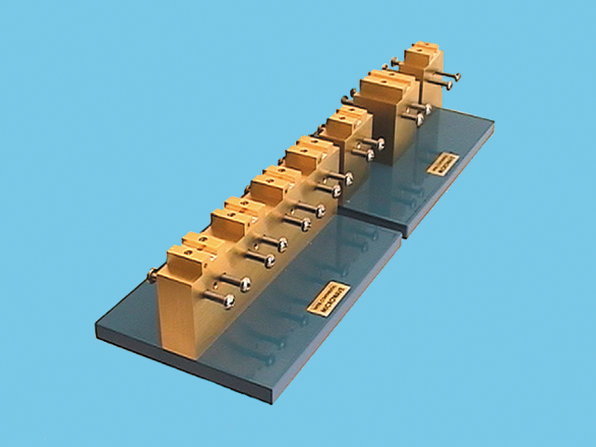
Calibration is another consideration with microstrip selection. The TRL\TOSL-2000 Series calibration kits, shown in Figure 2 , are designed to be used with the bolt-on transitions and to perform calibration from DC through 50 GHz (for TRL calibration) and DC to 6 GHz (TOSL calibration). They are based on alumina microstrip of different lengths and thicknesses. ICM offers a wide choice of standard microstrip materials including several popular Duroid laminates, FR4 and alumina of various thicknesses.
Regardless of the material chosen, the test fixture must be matched to the calibration kit in order to be able to de-embed the transitions and microstrip sections of the test fixture. The company's midsection adapters used for testing packaged transistors ensure that the reference planes are located in the correct locations. The midsection adapters have 25-mil alumina for the input and output lines, each with a 330-mil line length. When coupled with a calibration kit that has a 660-mil thru length (such as the TRL\TOSL-2004), it is possible to fully de-embed the transitions and midsection adapter while placing the reference planes at the interface of the DUT.
A typical RF package with microstrip input and output connections and DC inputs on each side is a good example with which to illustrate this do-it-yourself approach to test fixture development. The RF connections can be easily made with the bolt-on transitions, and the DC connections can be made with some PC board and simple DC probes made from spring-loaded contacts (pogo pins). The base for the DUT is a brass block that can be gold plated for greater electrical integrity and longer life. The mounting plate provides needed stability during the test.
Although the package is used only to 6 GHz, a conservative approach dictates that a higher frequency transition be used in order to investigate harmonics. As a result, a transition with an operating frequency of DC to 18 GHz is chosen. Of the possible choices offered by ICM, only the Type-N and 7/17-in. transitions do not meet this frequency requirement.
Since the measurement frequency will not be higher than 18 GHz, a 2.4 mm connector is not required; a 3.5 mm connector is acceptable. However, since the measurements must be conducted over the full temperature range of -55° to +125°C, the Super SMA transition is the best choice for this application.
The material choice is not important in this case because the signal is launched directly onto the device. However, the device uses 15-mil-thick alumina, so it is necessary to work with the 18-mil diameter RF pin and 15-mil wide trace width. The 15-mil-thick calibration kit will be used to calibrate-out the effect of the transitions, and the reference plane extensions on the network analyzer (in this case the Agilent 8510C) are used to make the measurements. They effectively move the reference plane back to the point where the RF pin contacts the device. The associated increase in return loss error is negligible. Two holes can be drilled on the topside of the block to accommodate DC probes. Once the primary components are selected and bolted together, measurements can be made immediately.
The TFC-Series starter kit contains two transitions, two DC-probe assemblies, a center block, a bottom plate, screws and instructions, and allows the designer to select from the same complete range of transitions and connector styles used by the main bolt-on product line, including the latest coplanar transitions.
Inter-Continental Microwave, Santa Clara, CA (408) 727-1596, www.icmicrowave.com. Circle No. 300