
With the evolution of LTE and the launch of 5G, the need for high capacity backhaul has become essential in mobile networks, due to the colocation of nodes, higher numbers of sectors and higher node coverage. Densification has reduced the distances between nodes, so much that over 50 percent of the nodes in a network are located less than 5 km apart (see Figure 1). Globally, more than 60 percent of base stations are connected with microwave radio links. The traditional frequency bands offer a limited and often noncontiguous addressable spectrum, capping the transport capacity. Moving up in frequency, however, offers larger spectrum bands.1
The E-Band allocation, from 71 to 76 and 81 to 86 GHz, offers 10 GHz total bandwidth, yet a shorter hop length because of path loss. From Friis’ formula, the higher the frequency, the more a radio signal is attenuated by propagation:
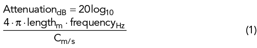
where c denotes the speed of light in air, approximately 3 × 10⁸ m/s. An 80 GHz communication link has 20 dB more attenuation than an 8 GHz link of the same length. Currently, E-Band radios have propagation behaviour similar to a traditional licensed microwave radio with a hop length comparable to that of a 38 or 42 GHz band. A 38 GHz link can achieve 2 Gbps capacity using a complex 4096-QAM modulation over a 224 MHz channel, which is the largest channel available in the traditional licensed microwave bands. In contrast, E-Band radios can reach 10 Gbps transport capacity over 2 GHz channels with much simpler 128-QAM.
Using E-Band boosts the mobile infrastructure capacity 5×, which will satisfy 5G transport needs. This increase has driven thesup adoption of E-Band, one of the top three frequency bands deployed globally in 2020.
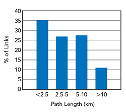
Figure 1 Distribution of backhaul link distances for a European mobile operator.

Figure 2 Cassegrain double-reflector antenna (a). Theoretical directivity and total HPBW of a three-foot parabolic antenna (b).
ANTENNA CHALLENGES
Typically, a Cassegrain parabolic antenna is used for point-to-point backhaul radio links (see Figure 2a). It is one of the simplest ways to use a large radiating area and focus the beam to a specific direction, which yields higher antenna gain.2 The directivity of the antenna is given by:
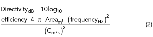
where the efficiency is usually around 0.7.
The higher the transmission frequency, the more directive the antenna beam becomes, as shown in Figure 2b.3 However, these narrower half-power beamwidths (HPBW) present a challenge for antenna alignment, which is exacerbated as the antenna diameter increases. A link is susceptible to misalignment, which can lead to signal deterioration and outages, reducing link availability. After the initial setup, misalignment can be caused by the sway of the mount in windy conditions and the twist of the mounting pole as it expands and contracts with daily changes in temperature.
Today, 80 GHz links mainly use antennas 1 foot (0.3 m) in diameter and have directivity of approximately 45 dBi. Replacing them with three-foot (0.9 m) antennas would increase the directivity to 54 dBi, an additional 2 × 9 dB combining the gains from the two antennas forming the link. This improvement doubles the hop length. However, the higher gain of the three-foot antennas increases the directivity of the beam and the requirement for tight angular alignment. Misalignment becomes critical, to the point of being practically unbearable: a one-foot antenna at 80 GHz has a HPBW of about ±0.5 degrees around boresight, while the HPBW of a three-foot antenna is only ±0.15 degrees.
A steering antenna can counteract environmental changes and maintain alignment, guaranteeing link availability and enabling the use of larger antenna sizes and longer hops. Both will aid the commercial adoption of multi-Gbps wireless transport.
MISALIGNMENT
Three environmental phenomena affect antenna alignment: wind vibration, wind plastic deformation and thermal deformation. The first, wind vibration can be addressed by proper site design. Since the effect of wind is a sway proportional to gust speed, plastic deformation can be modeled using the statistical distribution of wind speed in most urban and rural areas. The average effect is deemed negligible and no longer considered.