
One of the greatest challenges in characterizing new coaxial interfaces is to determine an accurate test configuration. When precision airlines are not available it is very difficult to obtain a true measurement of the device under test. It becomes necessary to design and implement calibration standards to eliminate the effect of adapters and validate the performance of the device.
This article discusses the design of a TRM calibration kit for the ZMA interface. The design was performed with the aid of Ansoft HFSS simulation software to characterize and optimize the calibration standards. The ZMA interface is a high coupling force bayonet connector used in microwave applications. Although the ZMA connector can be optimized to work up to 22 GHz, current requirements ask for a calibration kit up to X-band. Its performance is comparable to an SMA connector up to 12.4 GHz.1
The TRM calibration is an alternative to the traditional two-port error correction that uses short, open, load and thru standards (SOLT).2 The TRM offers equivalent accuracy and has the advantage that fewer and simpler standards are required.2-3 The name TRM represents the three standards that are used in the calibration - thru, reflect and match. The TRM calibration technique establishes the 12-term error correction for each frequency point.3
Systematic Errors in Network Analysis
The systematic errors that occur during microwave measurements are those that are repeatable and can be measured by a network analyzer. They introduce most of the measurement uncertainties. Since the systematic errors can be measured, however, they can also be corrected using calibration standards. A 12-term error correction like the one implemented with a two-port TRM calibration corrects for the following systematic error terms:
- Forward and reverse directivity EDF, EDR
- Forward and reverse reflection tracking ERF, ERR
- Forward and reverse load match ELF, ELR
- Forward and reverse transmission tracking ETF, ETR
- Forward and reverse source match ESF, ESR
- Forward and reverse isolation EXF, EXR
Figure 1 shows the six error terms associated with the forward calibration of a two-port circuit. To understand the effect of these terms on the measurement of a device, a simplified equation can be used for the worst case uncertainty of a reflection measurement.
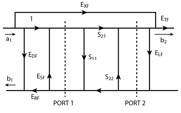
S11M = S11A±ED + (±ERS11A) + (±ESS11A2) ± ELFS21AS12A (1)
Here, Equation 1 shows that the measured value of S11M includes the actual S11A, the directivity, reflection tracking, source match and load match error terms.4-6 This equation does not take into account the phase of the error terms; therefore, it is the most pessimistic prediction of the uncertainty.
To illustrate the measurement uncertainty introduced by a test adapter, consider the directivity term, which is independent of the device to be measured. The directivity term is most significant for devices having a small reflection. It is the vector sum of all leakages and reflections including residual reflection effects of adapters and test cables.4 If an adapter with an input match SWR = 1.03 is used, a coupler directivity of 40 dB can be degraded to 32 dB. In the worst-case scenario, even a precision adapter with a very small reflection coefficient can introduce errors in the measurement.
Many vector network analyzers (VNA) have gating capabilities in which the effects of responses are selectively removed from the measurement. Although many users find it convenient for removing the effects of adapters, gating is a very complex operation. The accuracy of the gated frequency domain response is highly dependent upon the number of responses, the magnitude and separation of the responses, and how the gate is set up.4 Significant errors can be introduced if the gate is incorrectly positioned. Moreover, when precision airlines are not available, it is very difficult to obtain an accurate gated response.
ZMA TRM Calibration Standards
The TRM calibration process corrects for the 12-term errors by measuring three devices with known characteristics.2,3,5,7 The three devices or standards in the TRM calibration kit are thru, reflect and match. The ZMA TRM calibration kit contains 3.5 mm-to-ZMA adapters, male and female ZMA shorts, and male and female ZMA fixed loads.
The thru standard is measured when the 3.5 mm-to-ZMA adapter's test ports are mated. The reflect standard used is an offset short and the match standard is a 50  fixed load.
There are two main factors to be considered before designing a calibration kit. The first one is how precise the calibration standards can be manufactured. Although it is possible to characterize the standards with HFSS given dimension tolerances, it is more suitable to use only the nominal values. Therefore, all critical dimensions in the standards must be manufactured with a tolerance of +0.0002" from nominal.
The second main factor to be considered is the quality of the load. The return loss of the fixed load will significantly impact the quality of the calibration kit. When the network analyzer measures the directivity, it will include the actual directivity and the reflection of the load.4 High inaccuracy in reflection measurements will occur when trying to measure a device with a smaller reflection than that of the match calibration standard.
Design of the 3.5 mm-to-ZMA Adapters
The ideal thru standard is a device with zero length between the test ports. In the ZMA calibration kit, this is accomplished by mating the 3.5 mm-to-ZMA adapters. In order to perform the adapter replacement procedure to calibrate for non-insertable devices, all the adapters must have the same electrical length.
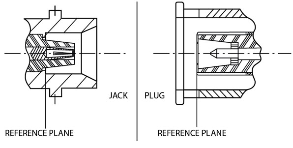
The location of the reference plane in the ZMA connector is at the outer contact mating surface, as shown in Figure 2 . When calculating the time delay for the ZMA male connector, the mated insulators and contacts must be included. Air gaps will occur as a result of the ZMA insulators mating. In HFSS, the 3D model of the adapters is drawn in the mated position, including all air gaps at the interface. Also, the female contact and outer contact of the ZMA interface are modeled in their closed position, which is a more realistic representation of the connectors during calibration.
Design of ZMA Shorts
The ZMA shorts are used as the reflect standard for the TRM calibration. For the short standard, only the offset phase and impedance need to be specified. The offset loss and inductance coefficients are optional.3,7
There are three main aspects that must be considered when designing short standards. The first one is that in order to reduce the effects of the offset and simplify the characterization, the short circuit must occur very close to the reference plane. Secondly, conductor materials and finish must be carefully selected to provide minimum loss. The last requirement is that the female and male shorts must be internally constructed as identical as possible. Ideally, the same standard should be used to calibrate both test ports.7
Since both female and male standards should be identical, the phase and impedance must be determined with very high accuracy using HFSS. The time delay was obtained in the same way as for the 3.5 mm-to-ZMA adapters.
The offset impedance was also obtained using HFSS. The post processor utility in HFSS indicates the impedance seen at the port. The impedance of the offset shortline should be very close to 50 and constant through the whole offset length. HFSS has the capability of plotting a TDR measurement that will indicate if there are any mismatches in the offset section.5 The HFSS TDR will plot the reflection coefficient versus time. Using Equation 2 and a spreadsheet program such as MS Excel, the plot is converted to ohms versus time.
Z = 50(1 + r)/(1 - r) (2)
Even though the inductance coefficients of the short are optional, HFSS can also be used to estimate their value. The inductance is modeled as a function of frequency using a third-order polynomial:
L0(nH) + L1(10-24H/Hz)f
+ L2(10-33H/Hz2)f2
+ L3(10-42H/Hz3)f3 (3)
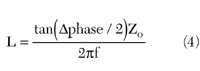
The HFSS post processor calculator is used to subtract the phase of the offset. Equation 4 is used to calculate the inductance at each frequency point.7 To obtain the coefficients, the resulting inductance is plotted using MS Excel and the polynomial curve fitting option.

Design of ZMA Fixed Loads
The fixed loads standards presented the biggest challenge. The difference between a TRL and a TRM calibration kit is that, when no precision airlines are available the fixed load is used as an infinite line. TRM was a better approach for the ZMA connectors because it is very difficult to obtain quality airlines when the insulator material at the interface needs to be included. Moreover, for a broadband application, such as 0.045 to 12.4 GHz, three airlines and a low band fixed load are required, increasing the number of standards. The challenge in designing the fixed loads was not only because they must have a very small reflection but also because female and male loads must be identical. HFSS was used to optimize a non-precision ZMA termination to a match calibration standard.
Verifying the Calibration Kit
There are various ways to verify the accuracy of the calibration. One way is to measure devices with known characteristics.4,7 To validate the performance of the ZMA calibration, four tests were performed. In each test the accuracy of the calibration is compared to the 3.5 mm calibration kit (85052B) from Agilent, which has already been validated.
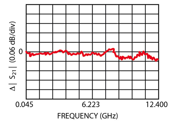
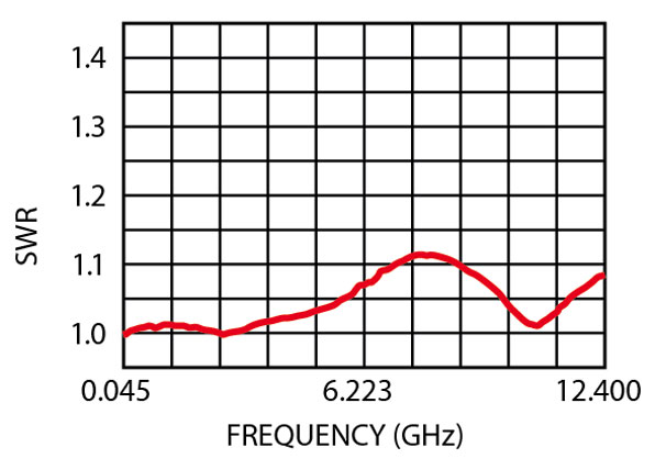
To test the transmission accuracy, a back-to-back mated pair of 3.5 mm-to-ZMA adapters were measured using a HP8510C VNA, calibrated with a 3.5 mm precision calibration kit. The adapters were mated at the ZMA interface. The transmission measurement was saved to memory. The same adapters were then measured after calibrating with the ZMA TRM calibration kit. The adapters were now connected at the 3.5 mm interface. The two insertion loss measurements were compared, as shown in Figure 3 . The maximum difference between measurements is less than 0.06 dB at the high end of the frequency band.

The first step when verifying the reflection measurement accuracy was to measure a 3.5 mm-to-ZMA adapter terminated with a ZMA load. The measurement was taken using a HP8510C VNA calibrated with the 3.5 mm calibration kit. A simulation with HFSS of the same adapter with the load was performed. The simulation result and measured data were compared. The simulation analyzes an idealized model of the adapter with the load. It is not taking into account tolerances or changes in the dielectric constant of Teflon with frequency. Therefore, some slight differences are expected between the actual data and the simulation results. This comparison, however, will establish a point of reference needed for the next step. The idea is that when the same load is measured after a ZMA TRM calibration, the discrepancies between simulation and actual data should be very similar to what was recorded in this step. Figures 4 and 5 show the HFSS simulation and measured data recorded for the adapter with the load.

The second step was to measure the same load after calibrating with the ZMA TRM calibration kit, which eliminates the effects of the adapter. The reflection measurement was then compared with a HFSS simulation of the same ZMA load without the adapter. Figures 6 and 7 show the HFSS simulation of the load and measured data after a ZMA calibration. The simulation results and actual data are very close. More importantly, the differences between the measured data and simulation results in this step were similar to the differences found in the first step when the adapter with the load was compared. The phase accuracy was verified by measuring a ZMA short with a different offset than the short standard used in the calibration.
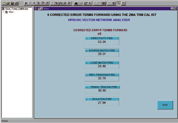
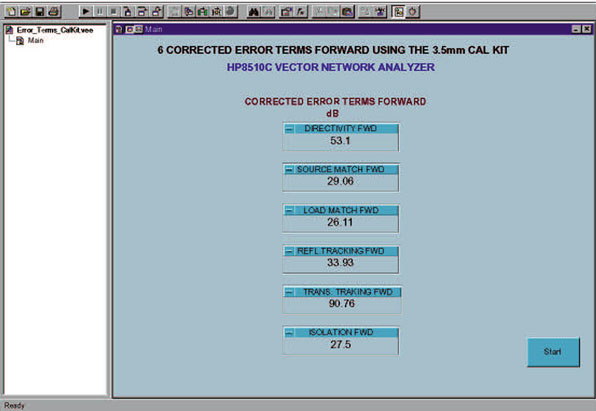
The final step is to compare the 12-term error values when calibrating with the 3.5 mm calibration kit and the ZMA calibration kit. The error terms will determine the accuracy of the calibration. The values were extracted using a customized program written in Agilent VEE. Figures 8 and 9 show the forward error terms after a calibration with the ZMA TRM and the 3.5 mm calibration kits. Both error terms are very similar.
The numbers can vary from calibration to calibration. Therefore, when extracting the error terms, the VNA must be kept with the same set up, that is, the same number of points, IF bandwidth and STEP or RAMP mode. Since these features will affect the accuracy of the calibration, they must be kept constant. These terms will determine the uncertainty of the VNA measurements. The measurement uncertainty for reflection measurements can be calculated using Equation 1.
Conclusion
The best method of validating the performance of new coaxial interfaces, such as ZMA, is by using a calibration kit of the same type of connector. Based on the results obtained when comparing the 3.5 mm validated calibration kit with the new ZMA TRM calibration kit, the ZMA calibration shows good agreement. HFSS proved to be a very useful tool in designing and characterizing calibration standards. It provides the advantage that the standards can be characterized without having to go through the iteration process of building and testing parts.
Acknowledgment
The author wishes to thank Judson Costas from SV Microwave Inc. for his help with the CAD drawings, and to acknowledge the assistance and support of Stavros Georgakopoulos and Denver Carnes from SV Microwave Inc., and Doug Rytting from Agilent Technologies.
References
1. J. Morelli, "ZMA: A High Coupling Force Bayonet Connector for Microwave Applications," SV Microwave Inc., October 2002.
2. "Network Analysis: Applying the 8510 TRL Calibration for Non-coaxial Measurments," Agilent Technologies, Product Note 8510-8A, May 2001.
3. J. Fleury and O. Bernard, "Designing and Characterizing TRL Fixture Calibration Standards for Device Modeling," Applied Microwave & Wireless , 2001.
4. "Basic Network Measurements Using the Agilent 8510 Network Analyzer System," Agilent Technologies, H7215A+140, Rev.5.0, pp. 1.12.1-2.3.10, October 998.
5. "Performing Time Domain Reflectometry in HFSS," Ansoft Corp., HFSS Engineering AP02-0101, 2000.
6. "In-fixture Measurement Using Vector Network Analyzers," Agilent Technologies, Application Note AN 1287-9, June 2002.
7. "Specifying Calibration Standards for the Agilent 8510 Network Analyzer," Agilent Technologies, Product Note 8510-5B, September 2001.
8. "Verifying the Performance of Vector Network Analyzers," Maury Microwave Inc., Application Note 5C-026, November 1997.
9. "Applying Error Correction to Network Analyzer Measurements," Agilent Technologies, Application Note AN 1287-3, March 2002.
10. "In-fixture Microstrip Device Measurement Using TRL Calibration," Agilent Technologies, Product Note 8720-2, August 2001.
Clara E. Centeno-Calero received her BSEE degree from the University of Puerto Rico, Mayagez Campus, and her MSEE degree from the University of Florida. She is currently a member of the product and market development group at SV Microwave Inc., where she is involved in the evaluation and design of new RF/microwave products. Previously, she held a hardware development position with Lucent Technologies, Bell Labs in North Andover, MA, where she was involved in the design of new products for the optical networking group.