

Ultra-wideband (UWB) communication, as standardized by IEEE 802.15.4, enables very low power communication and very accurate ranging in the license-exempt spectrum. Well established in several industry applications for years, the technology is now entering the consumer market. Testing of UWB devices is first of all related to regulatory requirements for ultra-wideband communication and UWB standard requirements. In addition, performance and interoperability aspects as covered by the FiRa certification program are of utmost importance. This article will give a brief introduction of the new 802.15.4z standard, followed by some guidance for the test and certification of UWB devices in research, development and production.
A short history of pulse radio communication
Pulse radio communication goes back to the early days of radio communications, as first demonstrated by Heinrich Hertz and Guglielmo Marconi more than 120 years ago. In the late 1950s, pulse radio was used in radar systems for marine systems. UWB communication as used in several applications today was first standardized in 2007 as alternative technology for low-rate wireless personal networks (LR-WPAN) in IEEE 802.15.4a-2007.1 In general, UWB communication systems are characterized by the transmission of extremely narrow pulses with a duration of few nanoseconds, which form an ultra-wide signal with a bandwidth of equal to or wider than 500 MHz – a characteristic that makes UWB signals relatively resistant to interference and allows very accurate time of flight measurements.
The high rate pulse repetition frequency (HRP) version of UWB was becoming quite successful in a wide area of industrial applications for ranging and low power device-to-device communication. In recent years, UWB has been entering additional application areas including consumer applications on mobile phones. Typical use cases are keyless entry, asset finding, indoor navigation, mobile data sharing and secure payment. In this context, in 2018 first the UWB alliance was formed to support the development of the growing UWB ecosystem, followed by the FiRa™ consortium in 2019. FiRa was launched by key industry players with the mission to provide seamless user experiences by using the secured FIne RAnging and positioning capabilities of inter-operable UWB technology.
Especially driven by the application demands for low power operation and secure ranging, the standard was further developed over the last years with the IEEE 802.15.4z Amendment “Enhanced Ultra Wideband (UWB) Physical Layers (PHYs) and Associated Ranging Techniques”.2
Secure ranging with IEEE 802.15.4z
In a nutshell, of all the additions to the standard, the three most important aspects of IEEE 802.15.4z-2020 addressing secure ranging are:
- Higher pulse repetition rates and optimized modulation schemes to improve power consumption and to allow reliable communication to ranges of up to 100 m.
- Secure ranging by cryptographic and random number generation used for scrambled timestamp sequence (STS).
- Specifying variants of two-way ranging procedures including simultaneous ranging.
Physical Layer
The standard distinguishes two UWB physical layers (PHY): the low rate pulse repetition frequency (LRP) and the high rate pulse repetition frequency (HRP). Figure 1 shows the operation bands for HRP and LRP. As can be seen, the HRP UWB PHY supports operation in three bands: a single 499 MHz wide channel in the sub-gigahertz band; four channels in the mid band from 3.1 to 4.8 GHz; and 11 channels in the high-band from 6.0 GHz to 10.6 GHz.
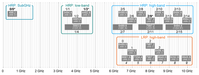
Figure 1. UWB operation bands for high rate pulse repetition (HRP) and low rate pulse repetition frequency (LRP).
The HRP UWB waveform is based on an impulse radio signaling scheme using band-limited pulses. The reference pulse is a root raised cosine pulse with a roll-off factor of β = 0.5. The duration of the pulses is in the order of two nanoseconds based on the maximum pulse repletion rate of 499.2 MHz.
In the new standard IEEE 802.15.4z -2020, UWB HRP PHY was extended for so called enhanced ranging devices (ERDEV) by a backward compatible physical layer working on the base pulse repetition frequency (BPRF) and a new physical layer using a higher pulse repetition frequency (HPRF), as Figure 2 shows.
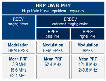
Figure 2. HRP UWB variants based on IEEE 802.15.4z-2020.
The BPRF physical layer applies a burst position modulation with binary phase shift keying (BPM-BPSK). In each symbol interval, a single burst is transmitted. This polarity-scrambled pulse burst can occur depending on the first bit output of the encoder either in the first or second burst position interval of the two halves of the symbol interval. The second bit output determines the polarity of the scrambled pulse sequences, that is generated as time-varying spreader sequence from a PRBS scrambler. In addition, BPRF is applying hopping between hop bust positions to avoid multi-user access interference. Figure 3 shows the modulation and coding principle for a BPRF signal exemplary with a burst of eight pulses within the first burst position at the first hop. Eight pulses during the symbol interval duration of 128 ns results in a mean pulse repetition rate of 62.4 MHz, which allows a data rate of 6.8 Mbps.
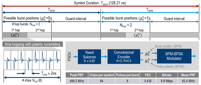
Figure 3. Modulation and coding of HRP UWB BPRF PHY.
Contrary to that, the HPRF physical layer applies a slightly modified modulation scheme for the higher pulse repetition rates of 124.8or 249.6 MHz. Pulse bursts are transmitted in both halves of the symbol interval. The polarities of the pulse bursts are defined by both encoder outputs using a mapping function as shown in Figure 4 and hopping is not applied.
For example, the two bursts of 4 pulses each per symbol interval duration of 32 ns result in the mean pulse repetition rate of 249.6 MHz. Depending on the applied coding (with or without Reed-Solomon coder) a data rate of 27.2 or 31.2 Mbps can be achieved.
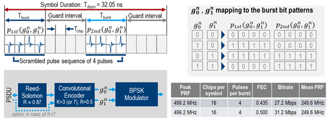
Figure 4. Modulation and coding of HRP UWB HPRF PHY @ 249.6 MHz.
In case of the second HPRF PHY variant with a mean pulse repetition frequency of 124.8 MHz, each burst consists of 8 pulses distributed over 16 chirps. Consequently, with the symbol interval duration of 128 ns (same as for BPRF PHY) data rates of 6.8 or 7.8 Mbps can be achieved.
In summary, higher pulse repetition rates and optimized modulation schemes introduced with IEEE 802.15.4z -2020 improve power consumption and allow more reliable communication to ranges of up to 100 m.3
Scrambled timestamp sequence for secure ranging
In order to enable secure ranging functionality, IEEE 802.15.4z introduced a sequence of pseudo-randomly generated pulses called scrambled timestamp sequence (STS) for enhanced ranging devices in HRP mode. The STS sequence is generated using an AES128 based deterministic random bit generator based on a seed value (128 bit STS key and data) aligned in advance between the transmitter and receiver using the secure private data communication service. The frame structure of HRP-ERDEV with STS in different positions is shown in Figure 5. The support for configurations 0, 1 and 3 are mandatory and configuration 2 is optional. The ranging marker (RMARKER) used as reference point for time measurements in the ranging procedure is the peak pulse location associated with the first chip following the start-of-frame delimiter.
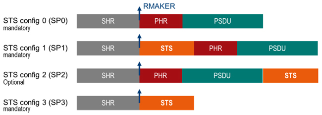
Figure 5. STS packet structure configurations of physical protocol data unit (PPDU).
One to four segments of STS sequences per STS are supported for improved security. For BPRF only one STS segment is supported, for HPRF the support of one or two segments is mandatory, three and four optional. With the STS also additional STS ranging makers (SRMAKER) are defined.
New variants of two-way ranging for time of flight measurements
The new standard describes several relative positioning and locating methods including single-sided and double-sided two-way ranging (SS-TWR, DS-TWR). Both methods use relative time measurements of the RMARKER at the antennas of two devices exchanging messages. The SS-TWR method is a kind of low-power variant with limited accuracy. It is using round-trip delay measurements of a single message exchange.
The operation of SS-TWR is shown in Figure 6. Device A initiates the exchange and device B responds to complete the exchange. The times TAround and TBreply are measured independently on the devices A and B using their local clocks so that no time synchronization between the devices is required. Based on the calculated propagation time Tprop – also known as time of flight (ToF) – it is possible to estimate the distance by multiplying with the propagation speed of the radio wave e.g. the speed of light.
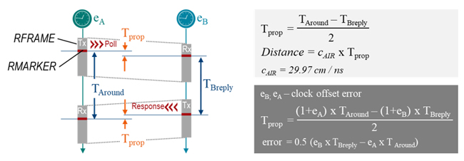
Figure 6. Single-Sided Time of Flight measurement.
The double-sided variant (DS-TWR) is an extension of the SS-TWR in which two round-trip time measurements initiated by device A and B are applied to get rid of the impact of clock offset error for more accurate distance measurements.