

TEST AND CERTIFICATION
Test and certification of UWB devices is of utmost importance to achieve regulatory conformance, interoperability, desired RF performance and accurate ranging results. In general, there are three areas of conformance related measurements to consider.
First of all, there is regulatory conformance based on related regional requirements e.g. specified in FCC CFR 47 Part 15.2504 or for Europe the specifications ETSI EN 303 8835 and ETSI EN 302 065.6 Typical measurement is the maximum allowable output power spectral density of -41.3 dBm/MHz.
Second, there are conformance requirements and recommendations defined in Section 15.4 RF requirements of IEEE 802.15.4. Besides typical RF measurements like spectral density measurements they include some specific measurements related to the transmitted pulse shape: For example, the measurement of a normalized cross-correlation magnitude of the pulses is used to check the main lobe duration and the maximum relative magnitude level of the side lobes. In order to improve the interoperability in ranging applications it is recommended that a transmitted pulse exhibits minimum precursor energy. Therefore, the standard defines a time domain mask as illustrated in Figure 7 that constraints the transmitted pulse shape accordingly. The peak magnitude is scaled to the value of one. The time unit is related to the defined pulse duration time Tp (e.g. 2 ns).
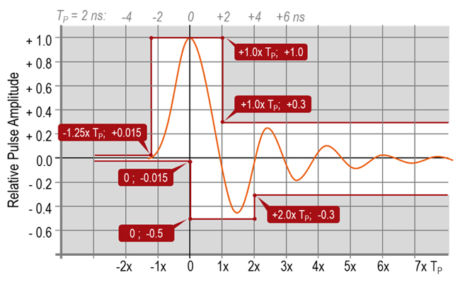
Figure 7. Recommended time domain mask for the HRP UWB PHY pulse.
There are a couple of other measurements of interest like chip rate clock and chip carrier alignment, transmit center frequency tolerance or normalized root mean square error (NRMSE) metric used to evaluate the transmit signal quality.
Third, there is the interoperability aspects driven by organizations like the FiRa™ consortium. For this purpose, FiRa has established a certification framework with conformance specifications for the physical layer and the MAC layer in line with the related UWB standards like IEEE 802.15.4z and extended by additional requirements important for the interoperability of ranging applications. Example for such additional test cases are the transmit signal quality (NRMSE), packet reception sensitivity, dirty packet receiver tests and first path dynamic range verification. Moreover, a common UWB command interface (UCI) for the testing of UWB devices was specified.
Test & measurement companies provide comprehensive UWB test solutions covering the full range from generating signals for any kind of receiver tests to analyzing the different UWB parameters in time or frequency domain of transmitted signals in R&D, integration, conformance and production testing. As an example, Rohde & Schwarzoffers a dedicated UWB signal generation option for the vector signal generators R&S SMW200A, R&S SMM100A and the R&S WinIQSIM2 signal generation software running on PC or in the cloud. Comprehensive UWB signal analysis functionalities are available on the spectrum analyzer R&S FSW and the vector signal analyzer software R&S VSE.
There are also dedicated wideband communication testers like the R&S CMP200, which provides all-in-one box for testing in production, R&D and FiRa conformance. The tester is complemented by a unique graphical user interface (see Figure 8) and enriched with a software for automated manufacturing. Moreover, the R&S CMP200 allows time of flight testing and calibration in conducted and over the air test setups.
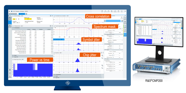
Figure 8. Graphical user interface of the R&S CMP200 tester showing UWB transmitter measurements
TIME OF FLIGHT TESTING AND CALIBRATION
Accurate time of flight (ToF) measurements – a key feature for many UWB applications – require ToF verification and calibration on the physical layer. The reference point for the time of flight related measurement is the antenna. Time measurements should start or stop when the RMARKER of a frame passes the antenna. In practice, the measurement will be executed inside the UWB chip before the frame is forwarded to the antenna, or after the frame was received from the antenna. This means the measured time needs to be adjusted depending on the time the signal is traveling from the chip to the antenna or vice versa. This onboard antenna delay depends on the concrete implementation e.g. length and material of wire and can slightly vary from device to device in production.
Measurements show that the onboard antenna delay can easily vary by 1 ns which could result in a ranging error of more than 30 cm. Therefore, it is highly recommended to perform a calibration in production. For this kind of measurement, a well-defined test setup applies a ranging procedure defined in 802.15.4z to measure the time of flight and calculate the calibration value.
For example, the R&S CMP200 acting as a UWB ranging device can initiate a single-side two way ranging procedure to perform these measurements. In preparation of this, it is necessary to calibrate the test setup to exactly determine the propagation time from the tester to the antenna of the DUT and vice versa. As shown in Figure 9, it is possible to calculate the correction value (Tad) based on TROUND value measured by the tester and Tre measured by the UWB device, when the exact time of flight between the coupler and the antenna is known.
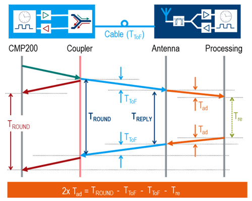
Figure 9: R&S CMP200 initiated ToF calibration.
Perspective
As a technology, UWB is celebrating a big comeback. The new 802.15.4z-2020 standard focuses on features that aim to address the real-world problems of the use cases. For example, the added security aspect helps to realize the remote keyless entry feature for UWB key fobs in the automotive industry.
In addition, the 802.15.4z-2020 standard introduced improvements in the radio (e.g. new PRF’s, enhancements for the PHY) and new ranging features which reduce power consumption and ensure interoperability among devices. Additional features like angle of arrival (AoA) will enable additional applications. The strength of the UWB technology is to enable reliable communication and excellent localization accuracy, which will also be a quality indicator for UWB devices. This, in turn, will make validation and calibration processes mandatory. Interoperability of UWB devices will be key for the success in an open UWB ecosystem and makes the UWB device certification efforts as driven by the FiRa consortium essential.
Adding to these characteristics the possibility to exchange data with good data rates, UWB is a strong contester to establish itself as the third big non-cellular technology besides Bluetooth and Wi-Fi.
References
1. IEEE 802.15.4a-2007
Part 15.4: Wireless Medium Access Control (MAC) and Physical Layer (PHY) Specifications for Low-Rate Wireless Personal Area Networks (WPANs); Amendment 1: Add Alternate PHYs; August 2007
2. IEEE 802.15.4z-2020
IEEE Standard for Low-Rate Wireless Personal Area Networks (WPANs)
Amendment 1: Enhanced Ultra Wideband (UWB) Physical Layers (PHYs) and Associated Ranging Techniques; June 2020
3. Rohde & Schwarz White Paper
High rate Pulse Ultrawideband physical layer testing and certification
4. FCC CFR 47 Part 15.250
Operation of wideband systems within the band 5925-7250 MHz, October 2010
5. ETSI EN 303 883
Short Range Devices (SRD) using Ultra Wide Band (UWB); Measurement Techniques;
6. ETSI EN 302 065
Electromagnetic compatibility and Radio spectrum Matters (ERM); Short Range Devices (SRD) using Ultra Wide Band technology (UWB) for communications purposes