
Figure 3 demonstrates the upper plate being rotated relative to the lower plate by some angle, Ψ. As seen in the figure, the wavefront of the guided waves between the two disks becomes inclined to the transverse stubs. This inclination between disks creates a phase delay between the radiated waves in each of the stubs and steers the beam in elevation.8 When both disks are rotated together, the antenna changes its scan angle in azimuth.
Disk rotation can be achieved in several ways including belt driven, perimeter gear driven, direct gear driven or through magnetic induction.8 More advanced VICTS antennas may have additional disks that serve to transmit or receive different polarizations other than the standard linear polarization of the basic VICTS architecture.7
One example uses a meanderline polarizer along with a grid line polarizer to change the polarization from linear to circular for transmit and from circular to linear for receive. A meanderline polarizer typically consists of at least one thin dielectric substrate layer on which conducting periodic meandering patterns are printed. The gridline polarizer is made using a similar structure and materials but consists of periodic parallel conducting traces. These two polarizers in the form of disks can be stacked on top of the VICTS apparatus with the meanderline polarizer above the gridline polarizer. The gridline polarizer pre-adjusts the angle of the linear polarization emitted from the VICTS antenna, ensuring an optimum axial ratio over frequency and scan, while the meanderline polarizer changes the polarization from linear to circular and vice versa. These two disks rotate as needed to achieve linear, right-hand or left-hand circular polarization while achieving an optimum axial ratio and impedance matching versus scan angle.9
Compared with the other flat panel antennas, VICTS antennas have a lower profile, a more simplistic design, higher radiation efficiency and fewer blind zones.7,10 Although VICTS antennas are mechanically driven, they have fewer moving parts than other mechanically-driven antennas and thus have reliabilities comparable to ESAs. This is especially true for VICTS antennas that use magnetic induction for rotation.8
In addition, VICTS antennas have minimal blind zones in which element coupling is significantly reduced in some scan regions.8 The blind zone in the VICTS antenna occurs when the beam is operating one to two degrees around the zenith, due to the wave propagating along the surface of the antenna instead of radiating outwards. Its large scanning range is an advantage over many 2D scanning phased arrays whose densely packed elements cause energy to be absorbed by adjacent elements when scanning at low scan angles.11 Furthermore, VICTS antennas use less energy and emit less heat than ESAs because they have less electronic components.8
LENS ANTENNA
A lens antenna is a type of phased array comprising modular lens sets that integrate radiating elements or feeds with lenses made of low loss dielectric materials shaped with specific curvatures. The gradient index (GRIN) lens is preferred in most applications due to its flat surfaces, wide scanning range and short focal length.12 Some applications use multi-layer composite dielectric lenses for ease of manufacturing with acceptable impedance matching and optical properties.
The optical properties of each lens set enhances directivity by focusing a plane wave to a small radiating element or feed at the RF front-end.13 This effectively downsizes the array number, reduce the overall cost of electronic components and DC power consumption. Most lens designs also enable optical off-axis focusing, which provides additional beam scanning flexibility for array operation. The overall antenna system, however, still uses an active analog or digital beamforming architecture for RF signal conditioning.
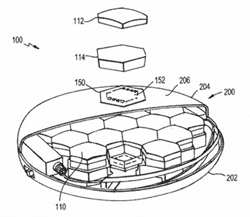
Figure 4 Cutaway view of a lens antenna.12
Depending on its architecture, a lens antenna can operate with two levels of beam scanning (coarse and fine beam pointing) to jointly steer the beam. Coarse beam pointing is executed by the lens set and front-end circuitry to create a directive broad beam that is steered by shifting the location of a feed element in relation to the focal point of the lens. This shift is either performed by electromechanical actuators or by electronically enabling or disabling feed elements within a small front-end feed array. Fine beam pointing is then done by combining corresponding feed elements in each lens of the array with phase shifts or time delays in the analog or digital beamforming networks.
The lens antenna architecture supports multi-beam operation in a single aperture. Multiple beams can be created by locating multiple feeds at different focal points of a lens. Each feed is connected to an individual RF circuit and associated network for independent beamforming. A large element spacing due to the physical size of each lens can create unwanted grating lobes. These grating lobes can be minimized by steering element patterns or by offsetting the phase center of each lens to break up the array periodicity.12
Figure 4 shows one concept of a lens antenna. Each lens set includes the lens (112), the lens spacer (114) and the feed set (150) with its respective feed element(s) (152).12 With this setup, each lens set is enabled as needed for multiple beams, high bandwidth and low power.14
The unique characteristics of the lens antenna provides advantages over a conventional phased array.16-17 With lens-assisted aperture directivity, it uses significantly less elements, reducing the active circuitry per beam for less power consumption and heat generation. In addition, some lens designs provide optical properties that enable elevation scanning with better directivity roll-off compared to the typical flat panel ESA.
TECHNOLOGY COMPARISON AND CONCLUSIONS
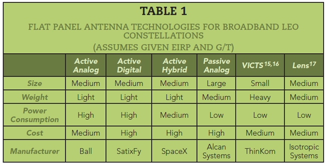
In Table 1, ESA, VICTS and lens antenna technologies are compared in terms of SWaP-C for LEO broadband communications constellations. Design challenges are identified for each.
A flat panel antenna’s ability to track and perform satellite-to-satellite handovers makes it a critical element of a broadband satellite system. Current Ku-/Ka-Band UT flat panel antennas are described and compared. The ESA’s multiple arrays of individual radiating antenna elements enables it to steer main and null beams toward specific locations with differences in strength and beamwidth depending on the number of radiating elements.
Three ESA beamforming techniques are analog, digital and hybrid. Analog beamforming is the simplest to implement, using one signal to steer the beam by shifting its phase for each antenna element. Due to its single RF chain, however, it can usually only steer one beam. Digital beamforming uses a dedicated signal for each antenna element, enabling independent control of multiple beams through baseband processing at the expense of prime power and cost. Similarly, hybrid beamforming accomplishes beam steering with a reduced number of RF chains combined with analog phase shifters. The combination of digital and analog beamforming techniques is limited to a smaller number of data streams but is less expensive than digital beamforming.
The VICTS antenna employs a simple structure of rotating mechanical disks allowing minimal blind zones while still radiating high energy.
The lens antenna’s modular lens allows for a lightweight terminal with different options in terms of gain, scanning range and relative transmit and receive performance.
References
- R. W. Nichols, J. S. Mason, G. M. Shows, J. C. Roper, R. D. Eppich, G. A. Burnum and I. Chang, “Active Electronically Scanned Array Antenna for Satellite Communications,” U.S. Patent 8, 334, 809, December 2012.
- J. Fruhlinger, “Beamforming Explained: How it Makes Wireless Communication Faster,” NETWORKWORLD, October 2019. Web. https://www.networkworld.com/article/3445039/beamforming-explained-how-it-makes-wireless-communication-faster.html.
- “What is 5G Beamforming, Beam steering and Beam Switching with Massive MIMO,” metaswitch, Web. https://www.metaswitch.com/knowledge-center/reference/what-is-beamforming-beam-steering-and-beam-switching-with-massive-mimo.
- A. Milne, “Understanding the Difference, and Debunking the Myths, Between Active and Passive Antennas,” RF Venue, December 2014. Web. https://www.rfvenue.com/blog/2014/12/15/active-v-passive-anntennas.
- M. N. Hamdy, “Beamformers Explained,” Commscope, 2020. Web. https://www.commscope.com/globalassets/digizuite/542044-Beamformer-Explained-WP-114491-EN.pdf.
- Y. J. Guo, J. D. Bunton, V. Dyadyuk and X. Huang, “Hybrid Adaptive Antenna Array,” U.S. Patent 8, 754, 810, June 2014.
- B. R. Elbert, “Aeronautical Broadband for Commercial Aviation: Evaluating the 2Ku Solution,” Application Technology Strategy, L.L.C., November 2014. Web. https://www.thinkom.com/wp-content/uploads/2013/08/Gogo_2Ku_Whitepaper_Rev2.pdf.
- W. W. Milroy, S. B. Coppedge and A. C. Lemons, “Variable Inclination Continuous Transverse Stub Array,” U.S. Patent 6, 919, 854, July 2005.
- W. Milroy and A. C. Lemons, “Linear to CP Polarizer with Enhanced Performance in Victs Antennas,” U.S. Patent 0, 313, 303, October 2020.
- M. Wei, J. Liu, H. Li and S. Liu, “Design of a Variable Inclination Continuous Transverse Stub Array,” International Symposium on Antennas, Propagation and EM Theory, December 2018.
- H. H. Vo and C. Chen, “Frequency and Scan Angle Limitations in UWB Phased Array,” European Conference on Antennas and Propagation, April 2014.
- C. P. Scarborough, J. P. Turpin and D. F. DiFonzo, “Lens Antenna System,” U.S. Patent 0, 269, 576, September 2018.
- J. P. Turmpin, C. P. Scarborough, D. F. Difonzo and J. Finney, “System and Method for Providing a Compact, Flat, Microwave Lens with Wide Angular Field of Regard and Wideband Operation,” U.S. Patent 0, 183, 152, June 28, 2018.
- “Solution: A New Class of Satellite Terminal,” Isotropic Systems, Web. https://www.isotropicsystems.com/solution.
- “Satellite Broadband Ka-Band Terminals,” ThinWave, Web. https://www.thinkom.com/wp-content/uploads/2020/05/ka-band-user-terminals_thinkom-solutions.pdf.
- “Satellite Broadband Ku-Band Terminals,” ThinWave, Web. https://www.thinkom.com/wp-content/uploads/2020/05/ku-band-user-terminals_thinkom-solutions.pdf.
- “The Isotropic Antenna: The Perfect Solution for Aero?” Satellite Mobility World, May 2020.