
In recent years, an increasing number of broadband satellite systems have been launched into low earth orbit (LEO), connecting people across the globe. Flat panel antennas are especially attractive for LEO satellites due to their tracking ability, low profile and easy installation. This article discusses three major antenna technologies: electronically scanned array (ESA), variable inclination continuous transverse stub (VICTS) and lens antenna. ESAs consist of arrays of individually controlled radiating antenna elements with different phase delays that coherently form and scan the antenna beam in the far field. Within the category of ESA antennas are analog, digital and hybrid antennas with passive or active radios. VICTS antennas consist of rotating disks that steer the beam and change polarization based on the relative position of the disks. Lens antennas consist of modular lens sets that steer the beam by individually controlling the source of energy relative to the focus of each lens. Each of these technologies has strengths and weaknesses that are compared in this article using the size, weight, power consumption and cost (SWaP-C) metric.
Since 2015, numerous satellite communications companies have designed and launched high throughput broadband systems to connect rural and underserved markets. These satellite systems have become more technologically feasible than those two decades ago, due to advances in wireless technologies as well as decreases in launch service and manufacturing costs. Non-cost prohibitive user terminals (UTs) and service plans, however, are required for a profitable broadband business, particularly in rural areas.
Ku- and Ka-Band satellite UTs require highly directive antennas to close RF links with satellites orbiting at altitudes of a few hundred to a few thousand kilometers above the earth’s surface. Fixed parabolic reflectors are commonly used for conventional geostationary (GEO) satellite systems, which do not necessitate tracking, as the satellite’s position relative to the user terminal is fixed over time. LEO constellations, however, require tracking and satellite-to-satellite handovers to maintain connectivity. These features, along with cumbersome mechanics and form factors, make parabolic antennas less attractive for LEO systems.
Flat panel antennas with low profiles and user-friendly installation processes have therefore become critical components in successful satellite broadband systems. This article discusses current Ku-/Ka-Band UT antenna technologies, describing ESA, VICTS and lens antenna architectures. It discusses advantages and disadvantages in terms of SWaP-C.
ESA ANTENNA
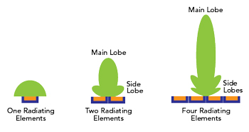
Figure 1 Antenna array gain and beamwidth depend on the number of radiating elements.
For LEO systems, an attractive alternative to the conventional dish antenna is an ESA, also known as a phased array antenna. An ESA includes an array of several individual sub-wavelength radiating antenna elements whose relative phases are controlled such that the overall beam from the array radiates in a particular direction due to constructive and destructive interference between individual elements.1 The process of constructing a concentrated beam using phased array antennas is called beamforming.2 The strength of the overall beam depends directly on the number of coherent radiating elements and the array configuration in the antenna; a higher number of radiating elements contributes to a narrower and more powerful main lobe with smaller and less powerful side lobes (see Figure 1).
Beamforming antenna systems can actively position their main beams and their nulls at specific angular locations using either analog phase shifters or digital coding algorithms. These beam steering techniques increase the throughput of the phased array without increasing transmit power.3
Three popular beamforming techniques are analog, digital and hybrid. While all three have have similar high-level architectures, there are two types of hardware implementations. Any of these beamforming techniques can be implemented using active radio components (e.g. RF amplifiers) external to the array or using integrated electronics (where the radios are embedded directly into the antenna array). A beamforming architecture with RF amplifiers built into the antenna array is called an active beamforming array. Beamforming architectures with external amplifiers or radios are called passive beamforming arrays.4
Active Beamforming
Analog beamforming is the most basic technique. It uses a single RF chain that connects each antenna element with amplifiers and phase shifters followed by splitters or combiners (see Figure 2a). The phase shifters, splitters and combiners are implemented using analog hardware. Beam shape and direction are controlled by digitally adjusting the phase shifters along the RF paths. Analog beamforming is usually more cost-effective and less complex than digital beamforming; however, it can effectively support only a single beam, being restricted to the same signal for each antenna element. Multi-beam transmission is possible, but it is tedious and complex.5 The antenna array is a full duplex (simultaneous transmission and reception), single aperture that uses frequency multiplexing with independently controlled transmit and receive channels for each radiating element.1
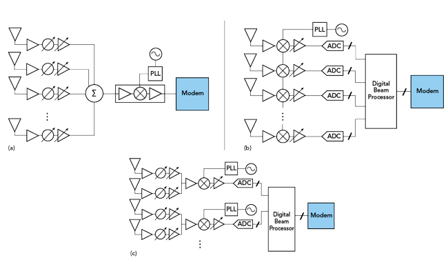
Figure 2 Receiver architectures for analog beamforming (a), digital beamforming (b) and hybrid beamforming (c).
Although digital beamforming is like analog beamforming, it differs in that each antenna element has a dedicated RF-to-digital signal and path, rather than a single common RF chain (see Figure 2b). Each individual path converts the RF signal to baseband (and vice versa) through RF mixers, ADCs and DACs. In this way, each path allows independent beam control, as phases and amplitudes can be controlled digitally through baseband processing. This increase in control allows multi-stream signal processing at the element level and enables the possibility to serve multiple users simultaneously through multiple physical beams.
One of the major challenges of the digital beamforming architecture is the distribution of local oscillator (LO) signals used for the mixers of each channel. The coherence of the LO affects the beam patterns and the system phase noise. In addition, digital beamforming structures consume high amounts of power due to demanding processor performance requirements.5
Hybrid Beamforming combines aspects of analog and digital beamforming. It uses digitally controlled RF chains that are further complemented by analog splitters and analog phase shifters (see Figure 2c). Fewer RF chains are therefore needed, which decreases total power consumption. The number of antennas used in hybrid beamforming are significantly higher than the number of A/D converters, which results in a smaller number of supported data streams. That said, hybrid beamforming is a reasonably priced alternative to digital beamforming because it consumes less power while still allowing multi-stream transmission.5
Figure 2c is a block diagram of the receive side of an active hybrid ESA. It comprises an array of antenna elements partitioned into multiple analog beamforming sub-arrays, a digital beamformer on the sub-array outputs and a control path back to the analog phase shifters. This reduces the size of the digital beamformer by a factor equal to the average number of elements in each sub-array. It provides an efficient means of producing large, high gain adaptive antenna arrays at relatively low cost.6
Passive Beamforming
Liquid-crystal (LC)-based passive beamformers have been designed for Ku/Ka-Band UTs. This type of array operates using the principle of phase delay in RF planar transmission lines on a LC substrate. By applying and controlling a DC voltage bias across the LC layer, one can adjust the alignment of the LC molecules in the substrate and change the associated dielectric constant to introduce phase delay to a signal on the transmission line.
Without active electronic amplifiers, the passive beamforming array has significantly lower DC power consumption than an active array, and a more straightforward antenna architecture as well. However, the passive antenna panel size is usually larger due to intrinsic losses of the LC and other PCB materials. The LC molecules’ time response (on the order of milliseconds) can result in slow array beam switching and cause temporary UT-satellite radio link interruption during handover in a LEO satellite system. The molecular response time also depends on operating temperature, so an additional heater may be required to maintain performance for operation in an extreme environment.
VICTS ANTENNA
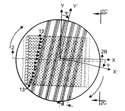
Figure 3 Top view of upper disk rotated relative to lower disk in a VICTS antenna.8
A VICTS antenna is a type of passive flat panel aperture antenna consisting of multiple stacked disks that mechanically rotate around a single axis to achieve azimuth and elevation beam scanning.7 The most basic VICTS antenna uses two disks, an upper disk and a lower disk. The upper disk has long parallel slits cut through it that enable electromagnetic waves to propagate. These slits are the radiating elements of the aperture and are known as continuous transverse stubs. The lower disk contains one, or more, line sources that produce electromagnetic waves. The space between the upper and the lower disk acts like a planar waveguide structure carrying the electromagnetic waves that feed the radiation.