Figure 2 illustrates why an element spacing of λ/2 is such a common metric in phased arrays. The antenna pattern is for a 64 element ULA antenna constructed with four subarrays. The center frequency is 20 GHz and the main beam is steered to an angle of 40 degrees off boresight. The blue curve shows the array pattern with a normalized element spacing (d) equal to 0.5λ. In red is the array pattern with d = 0.7λ. This results in a reduction in main lobe beamwidth and brings the nulls close together, but it also causes a replica grating lobe to appear at an azimuth angle of –52 degrees.
Beam Squint
When a wavefront approaches an array of antenna elements, there is a time delay between the elements based on the wavefront angle θ relative to boresight. For a single frequency, beam steering is performed by replacing the time delay with a phase shift. This works for narrowband waveforms, but for wideband waveforms, where beam steering is produced by a phase shift, the beam can shift direction as a function of frequency. Since time delay is a linear phase shift as a function of frequency, for a given beam direction the phase shift changes as a function of frequency. Conversely, for a given phase shift, the beam direction changes as a function of frequency. This change in beam angle as a function of frequency is called beam squint.10
Due to the time-delay-based nature of phase shifters, the beam is only perfectly steered at the center frequency; understeering is seen at the maximum operating frequency, and oversteering is observed at the minimum operating frequency. Phase shifters are preferred over time delay functions, however, due to the tradeoff between accuracy and circuit size. In fact, phase shifters provide adequate accuracy for almost all active electronically steered array applications, except for very wide instantaneous bandwidth applications or for very large arrays.9
Given that at boresight (θ = 0 degrees) there is no phase shift across the elements and thus no means to produce beam squint. Because beam squint appears and increases in intensity farther away from center frequency, it is a function of scan angle θ normal to the antenna direction as well as the frequency variation. Mathematically, beam squint is expressed as:

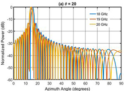
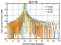
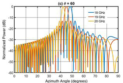
Figure 3 2D radiation patterns of beam squint for a ULA showing azimuthal cuts at θ = 20 degrees (a), θ = 40 degrees (b), and θ = 60 degrees (c).
Here, Δθ is the beam squint, ƒ0 is the center frequency, ƒ is the frequency at which beam squint is being calculated, and θ0 is the scan angle at center frequency.10 Figure 3 shows the elevation angle and frequency dependency of beam squint for a 64 element, eight subarray Ka-Band ULA antenna with λ/2 element spacing centered at 19 GHz and a modulation bandwidth of 2 GHz.
Scan Loss
The reduction in aperture gain when an antenna is steered to wide angles is called scan loss. Scan loss occurs due to a decrease in gain as an antenna’s scan angle deviates from the axis of maximum antenna gain, i.e., antenna boresight.11 Based on physical optics, scan loss can be interpreted as the inclined projection of an aperture and described by a cosine function.
Added to the loss due to optical projection, is the loss due to anisotropic radiation patterns of each array element. To include this, the cosine function is subject to a power term known as the cosine factor, ranging from 1.1 to 1.5, that depends on the characteristics of the radiating elements. The overall scan loss of a flat-panel aperture can be written as:

where θ is the scan angle from the aperture boresight and K is the cosine factor.
Field of View
Field of View (FoV) is the required scanning range for the UT to maintain radio links with satellites from handover to handover. FoV is directly determined by the constellation configurations, including, but not limited to the number of satellites, altitude, footprint and satellite look angle. FoV is also a function of each satellite's beamwidth.
Pointing and Tracking
Antenna pointing aligns the center of the antenna main beam on a target satellite. Tracking ensures antenna positioning to maintain pointing accuracy over time. There are several different tracking methods, which can be used independently or in conjunction with each other. A few of these methods include:
- Autotrack: Continuously aligns the antenna to an RF signal from the satellite in a closed loop system.3 Methods to track the signal include sequential amplitude detection and monopulse tracking.12
- Adaptrack: Creates a predictive model of satellite motion based on data previously collected from step-tracking.12, 13
- Program Track: The antenna follows a predicted trajectory of the satellite based on stored ephemeris data.12, 14
- Steptrack: The antenna searches for a maximum RF signal. It goes step-by-step changing its position around an axis. If the signal increases, it moves in the same direction; if the signal decreases the direction is reversed.12, 15
- Scan: The antenna rotates around an axis and moves according to variation in power from the received signal. This is used for initial satellite acquisition.12, 16
TERMINAL SYSTEM DESIGN CONSIDERATIONS
In addition to meeting technical performance requirements, user terminals of all types (parabolic and flat-panel arrays) must operate within applicable regulatory limits. The ITU is the global regulatory body that oversees spectrum use including allocations and regulatory limits. These regulations are established through a three year regulatory process, known as the World Radio Conference, to manage and limit harmful interference with incumbent and planned systems like Radio Astronomy Services and other existing (or incumbent) Fixed Satellite Service (FSS) networks.
Regulatory bodies, such as the US Federal Communications Commission (FCC) and UK’s Ofcom, function on a national level to ensure such use is aligned with the goals and priorities of individual countries or regions. While it is common for national limits to mimic those of the ITU, it is imperative to confirm designs comply with both international and national regulations.
Pertinent FCC Regulations
Key regulatory limits that pertain to the design of user terminals are specified in the forms of radiation masks; namely gain, EIRP and EIRP spectral density masks. Historically, user terminals, also referred to as earth stations (ES) operating in the FSS, including both non-geostationary (NGSO) and geostationary (GSO) systems, were subject to gain masks defined in Subpart C: Technical Standard of the FCC’s Part 25 Rules, specifically 25.209 Earth Station (ES) Antenna Performance Standards. Several of these masks take the form of either 29 to 25log(θ) or 32 to 25log(θ), where θ is measured in degrees from the boresight of the main beam, with varying levels further off axis to suppress sidelobes that could interfere with the other satellites. Historically, these masks were derived from the radiation pattern of a very small aperture terminal (VSAT), which typically uses an off-axis-fed reflector antenna with a non-scanning beam. Compliance is often challenging for panel antenna designs.
In 2015, the FCC updated their Part 25 rules, and specified that gain masks for Ku-/Ka-Band FSS systems be defined for ESs operating in GSO FSS systems as well as gateway ESs communicating with NGSO FSS satellites in Ku-Band. Gain masks are no longer defined in the Part 25 Rules for NGSO FSS user terminals, but it is important to note that the industry continues to report compliance with these masks on specification sheets.17
Pertinent ITU Regulations
While NGSO gain masks are no longer defined, NGSO FSS user terminals must operate with an EIRP mask that meets the complicated system-level, “equivalent power flux density up (EPFDup)” limits codified in Article 22 of the ITU’s Radio Regulation and in ITU-R S.1503. The EPFDup simulations consider the satellite constellation and UT operation parameters, including orbit geometry, number of satellites, minimum UT look angle and UT EIRP density patterns to compute the aggregated PFD toward the geostationary (GEO) arc. An EIRP spectral density mask is then defined through fundamental and physical analysis of the NGSO constellation’s potential to cause harm to GSO networks.
Other Pertinent Regulations
Other emission-related regulatory requirements include out-of-band and spurious emissions codified in ITU-R Recommendation SM-1539-1 and SM.1541-5. Additionally, European Telecommunications Standards Institute (ETSI) EN 303 980 and EN 303 979, specify the interference limitations into adjacent channels for Ku- and Ka-Band UTs, respectively. These harmonized standards require the use of additional filters and general state machines for UT operations to avoid exceeding unwanted radiation to other communication systems. Many of the requirements within these documents are also based on traditional VSAT-type parabolic dish antennas and are not suitable for phased array apertures that have different beam patterns and sidelobes over scan. As a result, the compliance methodology for flat-panel antennas is not thoroughly defined, and thus proves challenging.
CONCLUSIONS
LEO constellations and communication systems must be precisely designed to maintain connectivity, provide optimal performance and meeting regulatory requirements. Therefore, terminal antenna specifications that define these systems must be well understood. This article covers antenna parameters commonly used for LEO system operation and terminal design. Specifically, the definition of these parameters, their implications for system performance, and how they are used to indicate compliance with regulatory limits and required system performance.
Included are parameters that serve as figures of merit such as G/T and EIRP, parameters that describe an antenna’s behavior such as polarization and radiation patterns, parameters that can affect an antenna's performance such as grating lobes, scan loss, beam squint and tapering, as well as parameters that determine connectivity such as FoV, pointing and tracking.
Finally, Regulatory bodies are detailed along with key regulatory limits and requirements.
REFERENCES
- T. Milligan, “Properties of Antennas,” Modern Antenna Design, 2nd Ed. Hoboken, NJ, USA: Wiley, 2005.
- Guidelines for Determining the Effective Radiated Power (ERP) and Equivalent Isotropically Radiated Power (EIRP) of an RF Transmitting System, FCC, Washington, DC, USA, 2015.
- G. Maral and M. Bousquet, Satellite Communications Systems: Systems, Techniques and Technologies, 5th ed. Chichester, United Kingdom: Wiley, 2009
- J. J. Lee, “G/T and Noise Figure of Active Array Antennas,” IEEE Transactions on Antennas and Propagation, Vol. 41, No. 2, February 1993, pp. 241-244.
- “Introduction to Polarization,” EdmundOptics. Web. https://www.edmundoptics.com/knowledge-center/application-notes/optics/introduction-to-polarization/.
- “Antenna Polarization,” Electronics-Notes. Web. https://www.electronics-notes.com/articles/antennas-propagation/antenna-theory/polarisation-polarization.php.
- “What is Cross Polarization,” everythingRF. Web. https://www.everythingrf.com/community/what-is-cross-polarization.
- “Antenna Patterns and Their Meaning,” Cisco. Web. https://www.cisco.com/c/en/us/products/collateral/wireless/aironet-antennas-accessories/prod_white_paper0900aecd806a1a3e.html.
- I. Gresham and D. Corman, “An AESA Revolution Utilizing the Disruptive Technology of Highly-Integrated Silicon ICs,” Anokiwave Incorporated, 2018. Web. https://www.rellpower.com/wp/wp-content/uploads/2018/09/Anokiwave_AESA_Revolution_White_Paper.pdf.
- P. Delos, B. Broughton and J. Kraft, “Phased Array Antenna Patterns—Part 2: Grating Lobes and Beam Squint,” Analog Devices, 2020. Web. https://www.analog.com/media/en/analog-dialogue/volume-54/number-2/phased-array-antenna-patterns-part-2-grating-lobes-and-beam-squint.pdf.
- D. Corman, “A Comprehensive Guide to Active Antennas,” RF Global Net, 2018. Web. https://www.rfglobalnet.com/doc/a-comprehensive-guide-to-active-antennas-or-beamforming-0001.
- AC4100 Antenna Control Unit, ViaSat, Carlsbad, CA, USA. Web. https://manualzz.com/doc/14465192/ac4100-antenna-control-unit-datasheet.
- Model 8860 Antenna Tracking Controller, ViaSat, Carlsbad, CA. USA. Web. https://manualzz.com/doc/12596140/8860-antenna-tracking-controller-datasheet.
- Model 8861A/8862 Antenna Position Controllers, ViaSat., Carlsbad CA, USA. Web. https://manualzz.com/doc/9408678/8861-antenna-position-controller-datasheet.
- G. J. Hawkins, D. J. Edwards and J. P. McGeehan, “Tracking Systems for Satellite Communications,” IEEE Proceedings, Vol. 135, Pt. F, No. 5, October 1988, pp. 393-407.
- W. Gawronski and E. M. Craparo, “Antenna Scanning Techniques for Estimation of Spacecraft Position,” Proceedings of the IEEE Aerospace Conference, March 2002.
- Code of Federal Regulations, Part 25, Title 47, Federal Communications Commission. Web. https://www.ecfr.gov/cgi-bin/text-idx?SID=06858939fc9387440db08ece79c64479&mc=true&node=pt47.2.25&rgn=div5.
BIOGRAPHIES