
While space will push the boundaries of mmWave technology and communications, success depends on overcoming the challenges arising from the process.
In our spectrum-constrained world, the idea of going to higher frequencies, where spectrum is available, seems like a dream come true. For wireless systems ranging from 5G through satellite communications (satcom), mmWave offers that much-desired spectrum. For satcom, moving to mmWave promises advantages ranging from higher data throughput to finer range resolution from ultra-wide bandwidth. Of course, technology evolution always reveals new challenges. In space and satellite applications, these challenges are compounded by the pressure to drive down cost while accelerating design and manufacturing. As satellite systems add capabilities and reach new levels of performance, more uncertainty arises. Designers must pinpoint potential problems, verifying issues before launch to assure mission success.
Much of today’s mmWave focus is on 5G non-terrestrial networks (NTNs). Yet planning already has begun for 6G cellular. 6G satcom is predicted to meet the future surge in traffic while ensuring the performance needed for emerging applications. Success will rely on the use of mmWave frequencies, most likely combining terrestrial and NTN. As the industry builds on 5G NTN networks, it is already outlining the requirements and challenges for 6G. 6G success depends on first overcoming the challenges presented by moving to mmWave with the current satcom and 5G systems.
Wireless technologies increase signal bandwidth and use higher-order modulation to achieve greater data rates. Wider bandwidth is an attractive feature of mmWave communications, presenting opportunities for improved performance; however, wider bandwidth and higher-order modulation introduce challenges related to link quality at mmWave frequencies.
One major issue is the path loss a signal experiences when traveling through a medium like the atmosphere or a cable in the lab. Also, wide bandwidth devices are often difficult to implement and test in a system. The signal-to-noise ratio (SNR) may be lower, there may be more distortion and system components must have tighter margins. These contribute to the difficulty of getting a signal with high fidelity or accuracy.
TEST CHALLENGES
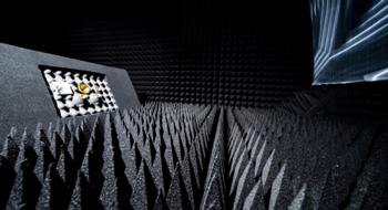
Figure 1 OTA test chambers are needed to test highly integrated mmWave components, which often lack physical connections.
For satellites, the ability to verify and predict real-world performance as accurately as possible is critical for ensuring mission success. The challenges impacting mmWave links also affect test capabilities. For example, excessive path loss between instruments and the devices under test (DUTs) results in a lower SNR, making signal analysis measurements challenging, such as error vector magnitude (EVM), adjacent channel power and spurious emissions. Complicating the measurement task, mmWave components are compact and highly integrated with no place to probe, requiring radiated or over-the-air (OTA) tests in an anechoic chamber (see Figure 1). With OTA testing, signal levels decrease dramatically, requiring that the test environment be designed and controlled. Path loss also complicates testing. At mmWave frequencies, RF power is limited and expensive, so measuring performance metrics using OTA test methods may limit the ability to achieve accurate and repeatable results.
The mmWave frequency bands offer wide bandwidths, which enable high throughput data, range resolution, accuracy and low latency. Yet they introduce more noise and increase test complexity and measurement uncertainty. Increasing the analysis bandwidth in a signal analyzer raises the noise floor, which reduces the measurement SNR. A low transmit signal may be masked by the noise floor within the channel, requiring better sensitivity at the receiver. These trade-offs make accurate mmWave measurements more challenging.
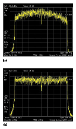
Figure 2 Poor (a) vs. flat (b) spectrum of an OFDM modulated signal
The frequency response of the overall system must also be considered. A test system’s primary objective is to characterize a DUT; the test system must isolate the DUT from all other test effects. The components between a signal analyzer and the DUT—mixers, filters and amplifiers—contribute to the overall frequency response of the measurement. The individual frequency responses contribute amplitude and phase errors which will degrade modulation quality, and these frequency response effects generally get worse when testing signals with wider bandwidths and at higher frequencies (see Figure 2).
BETTER MEASUREMENTS
Whether assessing transmitters, troubleshooting receivers or analyzing OTA signals, the flexibility of the signal analyzer’s hardware and software can help optimize the test setup. Input signals can range from high-power to noise-level signals, low frequency to THz and CW to complex wideband modulation. To measure this variety of input signals, signal analyzers should apply attenuation at higher power levels and use a preamplifier to boost lower power signals. Signal analyzers can be designed to provide various signal paths—default, microwave preselector bypass, low noise and a full bypass—to lower noise and improve sensitivity or reduce the signal path loss and increase the SNR (see Figure 3).
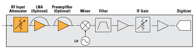
Figure 3 New signal analyzers help users optimize hardware settings to improve SNR and avoid overloading the digitizer.
A signal analyzer with these capabilities offers several methods to mitigate these test challenges and improve measurement results:
Analyzing wideband vector signals - The RF preselector in the signal analyzer most likely has limited bandwidth for image-free analysis. However, the bandwidth limits the RF analysis bandwidth. Bypassing the preselector enables wideband analysis with a flat response over the bandwidth of the digitizer. It improves amplitude accuracy, eliminating amplitude drift and the passband ripple in the preselector and enables wideband signals to be measured, such as 5G, satcom, IEEE 802.11ax/be and radar.
Strong out-of-band signals - When the input signal includes strong out-of-band signals, such as from a mixer with local oscillator (LO) leakage or spurs, the out-of-band signals can cause imaging and in-band interference within the analysis bandwidth, leading to failed measurements. A bandpass filter at the input of the signal analyzer can filter out these unwanted signals.
High power level - For testing transmitter modulation quality at high power, such as EVM, the signal analyzer may be set to a low noise path, which bypasses the preamplifiers and the lossy switches in the preamplifier path. At higher frequencies, the gain of the amplifier will decrease, and the insertion loss of the passive components will increase. A low noise path reduces this loss and eliminates the frequency response and noise from the preamplifiers and switches, improving signal fidelity and measurement sensitivity and yielding better wideband EVM measurement, particularly at higher frequencies.
Lower power levels - When testing at low power levels, such as an OTA setup, an internal or external preamplifier is necessary to increase the SNR for accurate modulation analysis.
Wideband modulation analysis - The full bypass path of a signal analyzer combines the low noise path with the microwave preselector bypass path. This setting eliminates the multiple switches in the low band switch circuitry and bypasses the microwave preselector. The full bypass path provides lower path loss, improving signal fidelity and measurement sensitivity. However, it may have disadvantages, such as in-band imaging and low SNR for testing at lower signal levels. Adding a bandpass filter to eliminate images in the measurement band can improve EVM measurements by 1 to 2 dB. Also, adding an external preamplifier can improve the SNR when testing lower power signals.
Insertion loss - In a mmWave test system, the cables and accessories between the signal analyzer and the DUT increase insertion loss. Cable loss can reach 5 dB, which will reduce the SNR of the measurement system. Adding an external mixer is a cost-effective way to extend the frequency range of the signal analyzer and move the mixer closer to the DUT, which shortens the signal routing, reduces loss and improves the SNR.
Production - mmWave test system integration and test costs create higher barriers when moving a project from R&D to volume production. A banded solution is a common approach to high volume production test. For example, an RF vector signal analyzer (VSA) and an RF vector signal generator (VSG) are essential for testing at the lower 5G frequency bands, i.e., FR1. For mmWave testing, i.e., FR2, the VSA and VSG can be used at the intermediate frequency (IF) and coupled with an external mmWave transceiver.
Using an external transceiver, the signal analyzer supplies a microwave LO signal to the external mixer and receives an IF signal from the mixer. The analyzer processes and displays the IF signal with filtering, digitizing and analysis, as it would with an internally mixed signal. New USB “smart mixers” simplify the connection and measurement, as the analyzer can detect the mixer, automatically download the conversion coefficient and monitor drive levels. External mixing provides a cost-effective solution for mmWave signal analysis and enables the test port to be located closer to the DUT. However, with this configuration there is no preselector at the front-end of the mixer, so strong out-of-band signals may create unwanted images in the measurement band and degrade accuracy. Also, if the test frequency is outside the mixer’s frequency band, the test signal must be reconnected to the signal analyzer’s RF input port or to another mixer covering the band, with the input source adjusted accordingly. These aspects increase test complexity and may affect measurement uncertainty.
All wireless standards specify that transmitter measurements should be performed at the maximum output power; however, the power at the first mixer of the signal analyzer may have to be attenuated to ensure the input signal does not distort the signal analyzer. With OTA tests and systems with large insertion loss, the input signal can be lower than optimum for the mixer. In these cases, the signal analyzer can use a built-in preamplifier, which provides better noise figure yet poorer dynamic range between the intermodulation distortion and noise floor. Another option is using an external low noise amplifier at the front-end, with or without the internal preamplifier, to achieve the best input level to the mixer. Setting the input mixer level is a trade-off between distortion performance and noise sensitivity, i.e., achieving better SNR with a higher input mixer level or better distortion performance with a lower input mixer level. The best level depends on the measurement hardware, characteristics of the input signal and specification test requirements.
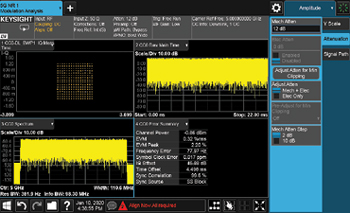
Figure 4 A built-in LNA reduces noise and two gain stages help balance noise vs. distortion.
Optimizing the SNR for the IF digitizer is another consideration. The system IF noise of a signal analyzer must be low enough to get the best EVM measurements, while the input signal to the digitizer must be high enough, yet not overload the digitizer. The optimum setup requires optimizing the combination of RF attenuators, preamplifier and IF gain for the measured peak signal. New signal analyzers have a single key feature which optimizes the hardware settings to maximize the SNR while avoiding digitizer overload (see Figure 4). The optimization process measures the peak signal level, then selects the best settings in the analyzer. Since the optimization period may not see the complete power characteristics of the input signal, the IF gain and RF attenuators can be tweaked manually to fine-tune for best results.
GOING FORWARD
The nature of satellite links creates challenges for RF designers. Beyond assuring communications performance, the system must perform reliably throughout the satellite’s life. Once deployed, a satellite cannot be called back for repair. This requires a level of assurance, whether the satellite is in geostationary earth orbit or part of a low earth orbit constellation. To address the challenges from higher frequency and wider bandwidth operation, more complex testing and characterization are needed to ensure the mmWave component and device measurements are accurate and the components and systems meet the demanding space requirements.
As the bandwidths and frequencies increase, the small margin of error allowable for measurements requires new ways to reduce errors. When the test setup includes connecting cables, connectors, switches and fixtures between the signal analyzer and the DUT, the measurement calibration should be extended from the signal analyzer’s input port (i.e., reference plane) to the DUT test port (i.e., measurement plane). Signal analyzers can perform internal calibration routines to correct for frequency response variations, providing complex amplitude and phase corrections to compensate. As more systems move to mmWave frequencies and eventually transition from 5G to 6G, mission success will depend on accurate measurements of device and system performance.