
In this application note, differential S-parameter measurements using a single-ended two-port vector network analyzer (VNA) and a pair of HYPERLABS ultra-broadband baluns are compared against measurements taken on a four-port VNA. The device under test (DUT) is a broadband differential amplifier. This application note builds on prior work reported by Picosecond Pulse Labs in application note AN-21.1. In the referenced note, Jim Andrews demonstrated differential S-parameter measurements to 10 GHz using PSPL 5310A broadband baluns. Using HYPERLABS’ broadband baluns, the same technique yields accurate differential S-parameter measurements to beyond 40 GHz from a single-ended two-port network analyzer.
TWO-PORT VNA MEASUREMENT SYSTEM
A block diagram of the two-port measurement system is shown in Figure 1. The VNA is an Anritsu MS4644B, and the baluns are HYPERLABS model HL9407. These baluns feature -3 dB bandwidth from 500 kHz to 67 GHz, ± 0.1 dB amplitude match to 30 GHz and ± 0.3 dB amplitude match to 67 GHz. To improve the impedance match of the differential test ports, 10 dB attenuators were added to each of the four differential test ports (see Figure 1).

Fig. 1 Two-port VNA measurement system.
The two-port VNA measurement system was constructed with a male differential test port 1 and a female differential test port 2. This arrangement facilitates zero-length thru calibration. The ports of the DUT were configured female-male accordingly. The connector spacing of the differential amplifier evaluation board does not match the connector spacing of the HL9407 balun, so it was necessary to use interface cables. Short semi-rigid VNA loops were employed to interface the incompatible connector spacings. One set of cables was incorporated into test port 1, and the other set of cables became part of the DUT.
TWO-PORT VNA CALIBRATION
A 12-term short-open-load-thru (SOLT) calibration was performed, including isolation, using two Anritsu 3652 “K” calibration kits. Each 3652 kit contains a female open, one female short, a male open and a male short calibration standard. Using two kits, it was possible to simultaneously connect two female calibration standards to differential port 1 for each set of short, open and load reflection calibration.
Figure 2 shows two female and two male open calibration standards connected to differential test port 1 and differential port 2, respectively. The calibration of port 1 and port 2 was completed simultaneously by cycling through the short, open and load reflection calibration standards. This approach eliminated the need to swap out equal phase test port adapters during calibration.

Fig. 2 Open-reflection calibration of port 1.
Only one calibration kit’s coefficients could be loaded into the MS4644B VNA. A small calibration error results from minor differences between the two calibration kits. The quality of the resulting calibration is shown in Figure 3, the active four-port measurement in Figure 4 and the defined DUT in Figure 5.

Fig. 3 Thru verification of the differential calibration.

Fig. 4 Active four-port measurement setup.
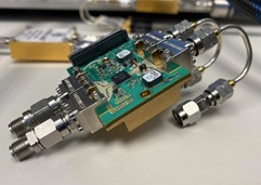
Fig. 5 Defined DUT.
FOUR-PORT VNA CALIBRATION AND MEASUREMENT SYSTEM
A block diagram of the four-port measurement system is shown in Figure 6. The VNA is an Anritsu MS4647B with MN4697C Multi-Port Test Set. Calibrations were performed using the Anritsu 36585V-2F Precision AutoCal.

Fig. 6 Four-port VNA measurement system.
After completing AutoCal, a thru update was performed for all port combinations shown in Figure 6 using an Anritsu 33VFVF50C female-to-female adapter (23.62 mm). The delay of the adapter was entered as a calibration coefficient and corrected by the thru update operation. However, the slight attenuation of the adapter was not corrected. As a result, insertion gain measurements taken on the four-port VNA measurement system are slightly optimistic.
S-PARAMETER TEST RESULTS
Measurements from both test systems are compared in Figure 7. The red traces represent data collected on the four-port VNA measurement system, and the blue traces represent data collected on the two-port VNA system using the HL9407 baluns.
 Fig. 7 Differential S-parameters measurements.
The |S11| and |S22| data from the two-port system is noisy and was smoothed with a 4.5 percent moving average in the plots. The raw data is presented in Figure 8. Port 1 is noisier than port 2, which may be related to the semi-rigid cables integrated into port 1 of the calibrated measurement system. The cables may have deformed due to torquing and flexing after calibration.

CONCLUSION
References
- James R. Andrews, “Differential VNA Measurements Using Single-Ended, Two Port Instruments and BALUNs,” Picosecond Pulse Labs Application Note, AN-21, Dec. 2008, https://kh6htv.files.wordpress.com/2015/11/an-21-vna-balun.pdf