
The evolution in cellular technology requires enhancements of its coaxial interconnections. This article explores the development and implementation of 4G/5G base stations with a discussion of their respective backhaul architectures and interconnects.
The xhaul architecture of cell towers has changed significantly since the time of early 2G/3G base stations with antennas connected through massive coaxial feeder links, now with highly integrated active antenna systems (AAS) for MIMO. Apart from the underlying radio protocols and hardware enhancements to meet growing traffic needs, these changes have invariably affected the choice and use of the interconnects used within these systems.
BASE STATION EVOLUTION
Earlier generations of cellular base station architectures were centered around the antenna installation connected to a remote radio unit (RRU) through long lengths (< 200 ft.) of coaxial cable. The other side of the RRU was connected to the base station processing or baseband unit (BBU) through a fiber-optic connection (see Figure 1). The separation of radio processing from the antenna system introduced significant coaxial cable losses. This called for power-hungry power amplifiers, with the necessary cooling and battery backups to overcome system losses, which reduced energy efficiency, cost-effectiveness and system scalability.
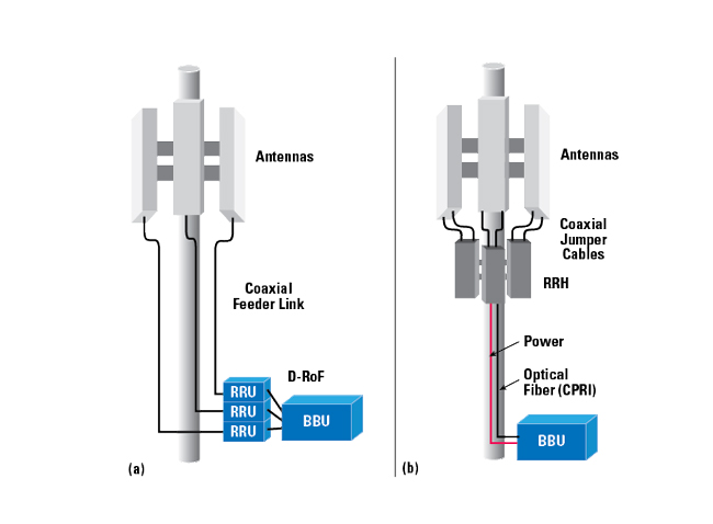
Figure 1 Cell site with a long coaxial feeder links between the antennas and RRUs (a) vs. fiber-based cell site with RRHs at the antenna (b).
Analyzing the efficiency of the base station, the power amplifiers contribute 50 to 80 percent of the total power consumption, followed by air conditioning (20 to 30 percent), signal processing (5 to 15 percent), and the power supply (5 to 10 percent).1 Later generations of cellular fronthaul brought the radio processing from the base station to the antenna structure. This remote radio head (RRH) was connected to the baseband processing through a fiber-optic connection via the Common Public Radio Interface (CPRI) protocol; this allowed the BBU to be located a larger distance from the RRH. The CPRI enabled a cloud radio access network (RAN), or C-RAN, where a single remotely-connected BBU or multiple remotely-connected BBUs, could run multiple cell towers. This, in turn, enabled much higher bandwidth and fronthaul distances up to 40 km.
INTERCONNECTS
Long lengths of coax come with design requirements, where the typical RG coax may not suffice. The attenuation, or loss per unit length, increases drastically, primarily based upon the choice of dielectric, cross-section dimensions of the coax and jacketing.2 The intrinsic loss within a coaxial cable is due to the loss tangent and conduction current within the dielectric material, as well as resistive loss within the metal. Dielectric loss can be minimized with a low relative permittivity dielectric material, which often translates to the use of foamed, or microporous, dielectric structures such as foamed polyethylene. Wider coax dimensions reduce resistive loss due to the marginally larger surface area of the inner and outer conductors.
Traditionally, 7/16 DIN connectors (IEC 60169-4 standard) have been the go-to connectors for base stations. These connector heads enable high power handling, low insertion loss, operation in harsh weather and good mating repeatability with screw-on coupling. However, straightforward coaxial installation is a major concern for mobile network operators. Either loose or over-torqued connectors installed by poorly trained technicians can cause significant signal degradation. Moreover, the process of mating connectors can lead to an unintentional torsional strain on the joints connecting the connector and cable, adding another source of loss. The use of these large connectors also fundamentally minimizes the available port density achievable per antenna; as base station antennas become smaller, so does the available space for connectors.
Signal distortion due to passive intermodulation (PIM) in the coaxial connectors of a cell tower is a major consideration for any of these base station iterations. PIM is typically found in passive components of high powered, multi-carrier systems, where mixing two or more signals occurs within the same transmission path, causing unpredictable frequency components to appear and interfere with the highly sensitive receivers. Typically, PIM is induced from metal-to-metal junctions or by the use of paramagnetic/ferromagnetic materials, both of which are found in coaxial connector heads. A connector that is not tightened enough or overtightened can result in PIM.
While low PIM versions of the 7/16 DIN connector are available, the 4.3-10 connector (IEC 61169-54 standard) was introduced to address the shortcomings of the 7/16 connector - with the mandatory requirement for low PIM performance. Low PIM can be achieved through careful selection of materials and reliable and repeatable connector mating. Nickel and chromium are ferromagnetic materials commonly used in coaxial connectors. Low PIM connectors avoid this potential source of PIM by using a non-ferromagnetic base with plating materials such as brass and silver or white bronze.