
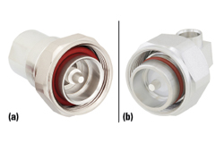
Figure 2 7/16 DIN connector O-ring with axial seal (a) and 4.3-10 connector O-ring with radial seal (b).
The nonlinear metal contact from inadequate mating or surface roughness is avoided in the 4.3-10 connector through a simplified mating methodology. This connector can mate either in a screw, hand screw or push-pull type configuration, where the hand screw and push-pull versions enable cable rotation in tight installation spaces. The 7/16 DIN connector requires a high level of torque to ensure both optimal electrical performance and a weather-tight seal. This is due to the “axial” seal formed when compression is applied to the top surface of an O-ring (see Figure 2). Because of this interdependence between the electrical and weather-tight connection, a strong electrical connection cannot occur without adequate axial compression of the rubber gasket. A 4.3-10 connector’s seal is accomplished through a “radial” seal, where compression is applied to the inner diameter of the O-ring. This effectively decouples the interdependence of the electrical connection and the mechanical mate, enabling a simplified hand screw or push-pull connection. Moreover, there is a 40 percent reduction in size without sacrificing power handling, insertion loss or VSWR.
In late 2016, the Next Generation Mobile Networks (NGMN) Alliance officially proposed migration to the 4.3-10 connector for new radio units and active antennas - 4T4R, pure time domain duplex (TDD) systems and hybrid TDD and frequency-division duplex systems - beginning in 2017, while the legacy systems could continue using the 7/16 DIN connectors.3
5G ARCHITECTURE
The 5G next-generation RAN (NG-RAN) architecture involves a functional split between a central unit (CU) and one or more distributed units (DU). This split can be cascaded with the addition of a separate radio unit (RU). Depending on anticipated traffic loads, expected data rates and latency, various potential RAN deployment scenarios will best serve the specific 5G use cases. These deployment scenarios can involve a separate CU/DU/RU, an integrated CU/DU, an integrated DU/RU or an integrated CU/DU/RU. This potentially splits the protocol stack at several points between every layer, including a physical layer/media access controller (PHY/MAC) split, MAC/radio link control (RLC) split or RLC/packet data convergence protocol split. Each of these have their own benefits and considerations.
Regardless, the split enables the low latency, high throughput communications required to support 5G, where the CU processes non-real-time protocols and the DU handles low latency, real-time traffic. The link between the CU and DU has necessarily evolved from the previously leveraged CPRI to an enhanced CPRI protocol supporting the intra-PHY functional split. The 5G gNB can vary between a small cell or a hot spot with an integrated CU/DU/RU, a macro-cell leveraging massive MIMO (mMIMO) and separate CU/DU/RU, a regenerative satellite functioning as a DU with a satellite link or a gNB CU and subsequent backhaul to the 5G core network (5GC).
MIMO
MIMO communications have been widely used to improve link reliability and network capacity through spatial diversity, with multiple antennas either transmitting the same signal over different paths (i.e., diversity gain) or transmitting multiple signals over different paths (i.e., multiplexing gain). This technology is expanded in 5G with mMIMO to drastically improve the wireless system spectral efficiency. Initially, the 3GPP LTE Release 10 included spatial processing techniques introducing transmission modes where the communication link is varied based on the capabilities of the base station (e.g., beamforming, single user MIMO, multi-user MIMO). 5G new radio (NR) expands on this with more channels compared to LTE: 4T4R, 8T8R, 16T16R, 32T32R, 64T64R and larger antenna counts for both passive and AAS. Beginning deployments for midband 5G NR use either TDD 8T8R passive antennas with calibration circuits and 16T16R, 32T32R or 64T64R active antennas.4
Due to the increase in port density per antenna, additional considerations for base stations implementing MIMO data streams are the increase in radios for each band and the control of PIM with the increase in potential sources.
The typical installation with passive MIMO involves a connection between radio ports and antenna ports through a series of jumper cables connecting the antenna to the RRH or RRU (see Figure 3). While this minimizes loss by eliminating the need for a long feeder cable, it increases the risk for errors due to installation, while also increasing the number of potential sources for PIM. This degrades signal reliability and dramatically limits the potential for scalability. For this reason, AAS are the go-to for larger MIMO systems where an integrated antenna/radio is used, eliminating the need for the jumper cables. For the AAS, only a fiber link and a DC power link are required for power, control and baseband processing. This, however, does not eliminate PIM. PIM optimization must be performed during the manufacturing process to meet specifications.
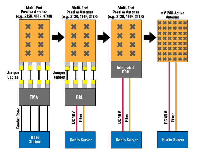
Figure 3 Cell site architectures showing connections between the antennas and radios.4
The implementation of large, passive MIMO systems calls for yet a smaller connector. The NGMN recently released a document in support of the MQ4/MQ5 connector for TDD 8T8R RRU and antenna configurations.5,6 The MQ4/MQ5 is a cluster connector that allows for increased port density with a straightforward, less error-prone installation, by combining multiple RF ports in one connector head. An eight-branch transmit and eight-branch receive (8T8R) system typically requiring 30 ports for a traditional coaxial connector head could be reduced to six to eight MQ5 or MQ4 ports, respectively. Other choices of connector heads in this specific MIMO application are 2.2-5 (IEC 61169-66) or NEX10 (IEC 61169-XX) type connectors, as well as the NEX10-compatible M-LOC connector.

Figure 4 Sample small cell installation. (Credit: Small Cell Forum)
The NEX10 connector features a 30 percent reduction in size from the 4.3-10 connector, low PIM performance (approximately -166 dBc) and operation to 20 GHz with either a screw type or push-pull mate. Once again, the NEX10 connectors de-embed the mechanical and electrical coupling mechanisms, allowing for a torque-independent electrical mate. The 2.2-5 series connector is 53 percent smaller than the 4.3-10 connector, with high PIM stability (approximately -166 dBc) and operation to 20 GHz with screw, hand screw and push-pull mates.
SMALL CELLS
The increasing density of small cells brings considerations of cost-effectiveness, mate repeatability and connection reliability. The NEX10 and 2.2-5 connectors are excellent candidates for the emerging small cell infrastructure to support 5G throughput/latency needs in dense urban environments (see Figure 4). The massive size reduction allows for simplified installation in tight spaces while also allowing for small cell functionality at frequencies up to 20 GHz.
CONCLUSION
The evolution in cellular technology has called for enhancements in coaxial interconnections. While the 7/16 DIN connector would suffice in the past, due to its mating repeatability and good electrical performance, it has limitations of large size and PIM. The 4.3-10 connector was introduced to guarantee low PIM performance while shrinking size significantly. Now, the increase in antenna port density due to large-scale MIMO installations and the shrinking size of base stations requires yet another level of integration and size reduction. This is where the 2.2-5 and NEX10 connectors, as well as cluster connectors such as the MQ4/MQ5, offer more viable solutions for 5G technologies such as mMIMO and small cells.
References
- L. M. Correia, D. Zeller, O. Blume, D. Ferling, Y. Jading; I. Gódor, G. Auer and L. Van Der Perre, “Challenges and Enabling Technologies for Energy Aware Mobile Radio Networks,” IEEE Communications Magazine, Vol. 48, No. 11, November 2010, pp. 66–72.
- Pasternack, “Designing Coaxial Cable Assemblies for High Performance and Reliability,” Microwave Journal, Vol. 63, No. 3, March 2020, pp. 6–12.
- “4.3-10 RF Connector Migration Strategies,” Version 7.1, NGMN Alliance, December 2016.
- “Advanced Antenna Systems for 5G,” 5G Americas, August 2019, Web. https://www.5gamericas.org/wp-content/uploads/2019/08/5G-Americas_Advanced-Antenna-Systems-for-5G-White-Paper.pdf.
- “Recommendation for RF Cluster Connector for Use in 5G NR 8T8R TDD Deployment,” NGMN Alliance, Version 1.13, August 2019.
- “Recommendation for RF Cluster Connector Antenna to Radio Module Pinout Alignment,” NGMN Alliance, Version 1.5, May 2020.