
Horn Lenses
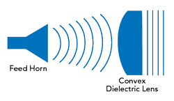
Figure 5 A convex dielectric lens alters the spherical or cylindrical wave from the feed horn aperture to form a planar wave.
Typically mounted at the aperture, dielectric lenses modify the radiation performance, often correcting the phase over a wide bandwidth or limited axial length. They also represent cost-effective alternatives to soft horns and corrugated horns, as lenses are much simpler to manufacture and mount onto the waveguide cap. The concept of focusing EM waves stems from the interference and diffraction light patterns of the Fresnel lens.
In general, convex dielectric lenses collimate incident divergent energy to focus a spherical or cylindrical wave front to a planar wave front, essentially controlling the taper of the field distribution, with the additional ability to shape the amplitude of the output EM radiation (see Figure 5). Typically, low permittivity and low loss tangent dielectrics such as Teflon, polyethylene, polypropylene, polystyrene and quartz are used to reduce the thickness and weight. Variants of the horn lens include constructing the horn solely of dielectric material. In this case, the phase errors at the aperture are higher than with a metallic horn, due to the lower propagation velocity, which ultimately reduces the achievable gain of these antenna structures.6 The typical gains of horn lens antennas fall between 30 and 40 dBi, with horizontal and vertical half-power beamwidths between 1 and 4 degrees and narrow bandwidths of approximately 1.1:1.
WAVEGUIDE PROBES
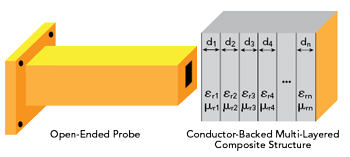
Figure 6 Open-ended probe radiates EM energy into the composite substrate, used for non-destructive testing.
Waveguide probes are ideal for near-field measurements such as non-destructive testing and evaluation. The relatively straightforward construction involves an open-ended waveguide with a finite flange and a signal source sends EM energy down the waveguide to the device under test (DUT). As shown in Figure 6, the EM energy propagates from the horn to penetrate the object in front of the open-ended waveguide. Understanding the dielectric properties of the DUT, the test can detect variations such as voids and cracks.
While this method can analyze materials in the field without disassembly (e.g., aircraft fuselages and radomes), it is not as accurate as measurements made with transmission lines. The waveguide aperture must be flush against the planar (or locally planar) dielectric substrate. Full-wave EM models are often generated to determine the reflection coefficient at the aperture of the waveguide, where it radiates into the dielectric structure. The accuracy of the technique is degraded with thin, low permittivity and low loss tangent materials; in such cases, alternative measurement methods using a probe station or test fixturing may yield better results.
OMNIDIRECTIONAL ANTENNAS
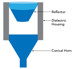
Figure 7 Omnidirectional waveguide antenna.
An omnidirectional radiation pattern can be generated with a waveguide antenna. This is often accomplished with the classical feed horn configuration propagating an EM wave in the TM01 or TE01 mode toward a metallic conical reflector a predetermined distance from the conical waveguide aperture (see Figure 7). The conical reflector radiates the energy horizontally 360 degrees around the axis of the reflector, creating an omnidirectional pattern. The parabolic shape of the reflecting surface, in turn, creates a phase correction for the reflected spherical wave.7 This structure is often placed within a dielectric holder made of a low loss tangent material, to maintain the distance between the waveguide and the reflector.
SUMMARY
The combination of high power handling capability, directionality and mmWave coverage makes waveguide antenna structures pertinent for contemporary RF and mmWave systems, particularly with increased use of the mmWave spectrum. Understanding the basic performance of waveguide antennas can be useful when choosing an antenna for a mmWave system or test setup.
References
- A. Macikunas, S. Haykin and T. Greenlay, Trihedral Radar Reflector, 1984, US4843396A.
- W. Chen, The Electrical Engineering Handbook, Elsevier, 2004.
- R. Poisel, Antenna Systems and Electronic Warfare Applications, Artech House, 2012.
- J. Volakis, Antenna Engineering Handbook, McGraw-Hill, Fourth Edition, 2007.
- J. De Miguel-Hernández and R. J. Hoyland, “Fundamentals of Horn Antennas with Low Cross-Polarization Levels for Radioastronomy and Satellite Communications,” Journal of Instrumentation, Vol. 14, No. 08, August 2019.
- J. Thornton and K. C. Huang, Modern Lens Antennas for Communications Engineering, John Wiley & Sons, 2013.
- G. Dienes, Broadband Omnidirectional Microwave Antenna, 1995, EP0678930A2.