
In the past, the vast mmWave spectrum was used sparingly, compared to today’s onslaught of new mmWave applications: the recent WiGig standard (802.11ad) in the 60 GHz ISM band, the many new 5G mmWave frequency allocations, Ka-Band and beyond space transponders for higher satellite capacity and many new radar applications, including 77 to 79 GHz automotive radar. Although many of these use cases use planar antenna structures, waveguide antennas are critical for system characterization, and waveguide antennas are used in radar, point-to-point communications and many more applications. While a library of literature is dedicated to the theory behind these antennas, this article provides a general discussion, intended to be useful when considering the range options for various applications.
CORNER REFLECTORS
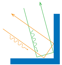
Figure 1 Corner reflectors scatter a signal back toward the source.
Corner reflectors function on the principle that incident electromagnetic (EM) waves reflect off conductive sheets in a direction parallel to the incident beam and with the same polarization as the incident wave. This, in effect, reduces the cost of a radar or communications system, as signal transmission does not require a power supply or any additional components often found in a transmission chain (e.g., mixer, LO, amplifiers, filters, converters).
The corner reflecting antenna can either be in a dihedral or trihedral configuration. In the dihedral topology (see Figure 1), two highly reflective plates are perpendicular to one another and scatter a signal back toward the source, increasing the radar cross section (RCS). Following the same logic, a trihedral antenna structure uses three reflective surfaces joined at right angles. In this case, a reflected wave can theoretically arrive from any direction and still be returned directly back toward its source.
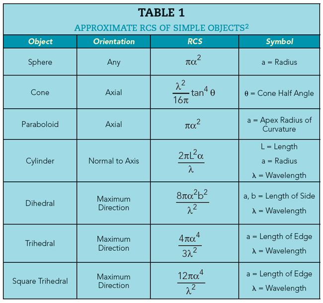
This is particularly useful in point-to-point marine navigation, where ships can accurately determine their relative positions from an interrogation via precisely placed reflectors, known as monostatic scattering.1 The backscatter cross section is straightforward to determine due to the simple geometries of the corner reflectors. In this way, the RCS remains high over a wide range of incoming wave angles. Table 1 shows the approximate RCS of some objects in the resonance region, where the dimensions of the object are large compared with the wavelength of the signal. In these cases, the RCS can be approximated by the product of the effective gain of the object and its physical area.2 For example, the RCS for a triangle reflector at 30 GHz (λ = 10 mm) and a corner length of 6 in. is about 22 m2.
APERTURE ANTENNAS
Aperture antennas are particularly useful in aerospace applications, as they can be flush with the skin of an aircraft or spacecraft. These antennas provide gradual transitions from the radio and transmission lines or waveguide to free space, with impedance matching between the aperture and the waveguide, as well as between the aperture and free space. Table 2 shows the gain and beamwidth of some common waveguide aperture antennas.
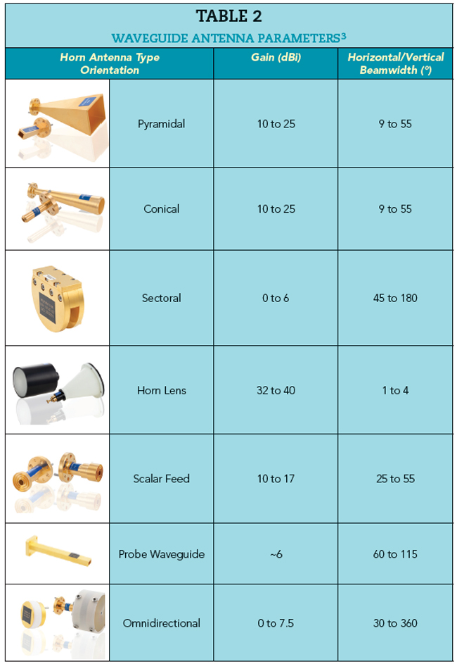
The horn antenna is a popular choice for high gain and directivity for radar and mmWave applications. It has a large aperture tapered at one end with a waveguide flange to connect to the antenna feed. Variants of the horn antenna include pyramidal, sectoral, conical, scalar (exponential), corrugated, gain and feed. The horn acts as a guiding system from the waveguide mode to free space, where the axial length and aperture can be adjusted for optimal gain and directivity.
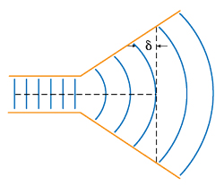
Figure 2 Radiation from a horn antenna.4
The EM field is determined by solving Maxwell’s equations to satisfy the boundary conditions at the conducting walls of the horn for the fundamental and higher order modes. The horn should be considered separately, versus applying waveguide aperture antenna theory, as phase errors occur from the difference between the length along the center of the feed versus the length to the horn edge (see Figure 2). The field lines shift from the dominant mode planar wave to a curved wave front, where the path difference between the curved wave front and the ideal plane wave creates a phase difference or error that must be addressed mathematically.4 Approximations for radiation patterns, given antenna dimensions, have been developed for various horn antennas; using them, the antenna gain can be closely matched to calculations, assuming precise manufacturing.
In the waveguide-to-horn transition, the plane EM wave front (TE10 or TE01 for rectangular waveguide) shifts to a curved wave. This wave front - cylindrical for a sectoral horn and spherical for a conical horn - emanates from the horn, and the flaring imparts directionality: a wider flare provides a wider beamwidth and lower gain, compared to a smaller flare with higher gain due to the smaller beamwidth and more focused beam.
For a sectoral horn (see Figure 3), a fan-shaped beam is generated in the plane containing the flare. Generally, rectangular horn antennas such as pyramidal and rectangular have the downside of significant sidelobes, and the abrupt transition from waveguide to flare predominantly contributes to the overall reflection coefficient. This leads to using nonlinear flaring configurations (i.e., a soft horn), such as corrugations, dielectric wall linears or strips laid out transverse to the direction of propagation of the EM field.
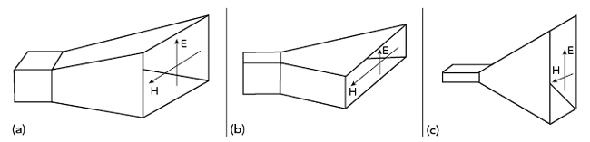
Figure 3 Rectangular horn antennas: pyramidal (a), H-plane sectoral (b) and E-plane sectoral (c).
Conical Gain Horns
The conical gain horn antenna generally has a much narrower bandwidth compared with its rectangular counterparts; however, because of its axial symmetry, the conical horn can handle any polarization of the dominant TE11 mode and is particularly useful for applications that require circular polarization (e.g., space communication). Like the rectangular horn antenna, the circular horn uses a flare to achieve a smooth impedance transformation. Typical gains are between 10 and 25 dBi, with horizontal and vertical half-power beamwidths between 10 and 60 degrees and narrow bandwidths - 1.3:1 maximum, compared to 2:1 for rectangular horns.
Scalar Feed Horns
Aside from more complex manufacturing processes and higher associated costs, scalar feed horn antennas offer high power handling capability and high directivity with low loss over a wide bandwidth. They are ideal as antenna feeds for radar and communications systems, such as radio telescopes that use parabolic dish reflectors, as they are able to provide relatively even illumination of the surface while minimizing signal leakage past the reflector, maximizing overall antenna efficiency. The radiation pattern of the feed antenna must be customized to the specific shape of the parabolic reflector.
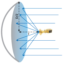
Figure 4 Wide angle scalar feed horn in the focal plane of a parabolic dish reflector.
For antenna patterns in the far field, the desired polarization is known as co-polarization while the orthogonal component is known as cross-polarization.4 Cross-polarization is particularly relevant for parabolic dish reflector feed horn antennas because the feed aperture is typically located at, or slightly in front of, the reflector focal point, which is the theoretical point where all incoming rays parallel to the paraboloid axis are reflected through the focus (see Figure 4). The wide angle scalar feed horn in the focal plane of parabolic dish reflector must exhibit a uniform radiation pattern in the far field to minimize cross-polarization and maximize overall antenna efficiency.
Scalar feed horns take advantage of a hybrid mode of propagation to achieve high axial beam symmetry, low sidelobes and low cross-polarization. The hybrid mode differs from the TE or TM modes of propagation within a waveguide, as neither the electric nor magnetic fields is purely transverse to the direction of propagation. In the hybrid mode, or balanced hybrid, condition, symmetric E- and H-plane patterns are generated where the TE and TM components are matched in a singular hybrid mode and propagate with a common velocity. In this way, the paraboloid receives the complete field pattern from the feed with uniform fields across the aperture of the reflector.5 Linear E-fields cannot be produced by a radiation pattern purely TE or TM mode; corrugations in the horn modify both the electric and magnetic fields to satisfy the hybrid mode condition.