Normally, the most talked about aspects of 5G in the RF front-end are the deployment and functionality of massive MIMO (mMIMO), mmWave transceivers for small cells and the power density requirements of power amplifiers (e.g., silicon versus GaN). However, the key performance indicators of 5G impact other components in the RF front-end transmit/receive chains, particularly oscillators, where timing and synchronization requirements drive the need for more precise oscillator design and fabrication.
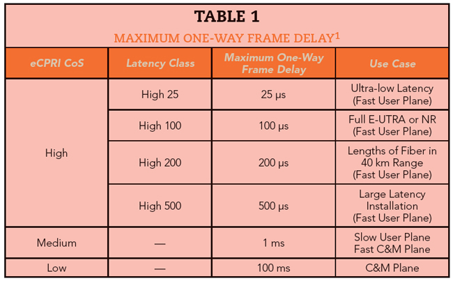
Cooperative radio techniques such as inter- and intra-band carrier aggregation (CA), MIMO, downlink coordinated multi-point (CoMP) transmission and reception and uplink CoMP require much tighter synchronization than traditional 4G technologies. The entire synchronization chain, including the air interface at the remote radio unit (RRU) and introduced errors from fiber, switches and routers at various nodes must be considered. The end-to-end (E2E) latency for time-division duplex (TDD) 5G networks is 1.5 μs; this, however, is only a foundational latency requirement that gets progressively tighter with cooperative radio techniques. The newly introduced enhanced Common Public Radio Interface (eCPRI) protocol has made provisions for this, which makes official the increasing importance of a stable source for an effective 5G network.
5G xHAUL: CPRI CONSTRAINTS
Previous generation cellular base stations comprised a baseband unit (BBU) and remote radio head (RRH) connected to the antenna through a run of coax. The RRH handled the conversion between the digital and RF signals, while the BBU handled the bulk of the processing by providing the physical interface between the base station and the core network.
The LTE base station (eNodeB) improved this with an integrated antenna and RRH connected to the BBU through an optical fiber using a CPRI signal, eliminating RF cable loss and interference. The 3GPP new radio architecture now consists of a centralized unit (CU), distributed units (DU) and RRUs, where the 4G BBU functions are split into the DU and CU. This network architecture (see Figure 1) includes fronthaul, midhaul and backhaul infrastructure to handle the capacity, latency and reach requirements of 5G. Instead of the CPRI interface between the BBU and the RRH in 4G, 5G fronthaul architectures will likely leverage the eCPRI interface between the DU and the RRU. The eCPRI protocol, however, is not limited to fronthaul; it can service connections between the CU and DU.

Figure 1 5G Location of fronthaul, midhaul and backhaul in the network.
Wireline Solutions: CPRI vs. eCPRI
The CPRI protocol is a standard digitized format mainly used to transfer point-to-point data over fiber to separate the radio equipment (RE) from the radio equipment control (REC). This enables the 4G eNodeB configuration with a BBU (REC) separate from the RRU (RE), which is often integrated with the antenna. However, CPRI does not scale well with base stations that have a functional decomposition - specifically, a functional split within the physical layer (intra-PHY split). The intra-PHY split is necessary in 5G, enabling high data rate functions such as CA, network MIMO, downlink CoMP and uplink CoMP. This led to the release of eCPRI, with the goal of “decreasing data rate demands between eREC and eRE via a flexible functional decomposition.”
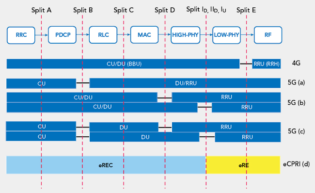
Figure 2 CU, DU and RRU functions in high layer (a), low layer (b) and cascaded split points (c), with the corresponding intra-PHY eCPRI split (d).1,2
Figure 2 shows the functional split in various 5G architectures described in ITU-T GSTR-TN5G, as well as the intra-PHY downlink splits (ID, IID) and uplink split (IU) specified in eCPRI.1 More often than not, an eRE corresponds to an RRU, while the eREC includes the CU and DU functions.