
A system is composed of four elements: an RF payload, a receiver system, a drone and a base station, as shown in Figure 2. The RF payload comprises an antenna and a signal source. The signal source must be characterized by a stable frequency level and power output. The antenna must have a high level of cross-pol isolation and preferably have some gain and directivity to minimize the effect of interference coming from the environment. The ability to cover a broad frequency range is required to ensure that a wide range of different antennas can be tested. The purpose of the RF payload is to illuminate the antenna under test with a plane wave. The ability to precisely point the RF payload at the antenna under test is paramount.
A receiver system coupled to the antenna under test determines how much power is received by the test antenna. A spectrum analyzer or a power meter can be used. The receiver system also requires an amplifier to ensure that the signal is well above the noise floor in the measurement device.
The drone replaces the positioner in the standard antenna measurements and is accurately transporting the RF payload during the measurements. An advanced flight computer and pre-flight path planning software are required to create a spatial link between the system and ensures accurate control over the flight. It is crucial, that a flight path can accurately be replicated to provide measurement reproducibility. The flight sensors, onboard the drone, are vital for providing the necessary information to plot the conclusive results, as well as to compute the measurement uncertainty, which can subsequently be removed or quantified and documented.
A base station is required for real-time monitoring of the flight as well as other controlling functions that are key during the test, such as change of parameters or error correction with the position navigation and timing (PNT) system. Using a real-time kinematic (RTK) PNT base station allows for the drone to fly very accurately in the local reference system of the antenna under test. The RTK PNT used by QuadSAT ensures a drone position accuracy of 2 cm horizontally and 5 cm vertically. To put that into perspective, with this knowledge the drone will be able to maintain its position within a 30 x 30 x 30 cm box (see Figure 3), even in high winds, up to 33 mph (54 km/h). This implies a pointing accuracy which is better than 0.01 degrees relative to the antenna, which rivals the accuracy provided by traditional, high performance, far-field test ranges.
PRACTICAL IMPLEMENTATION
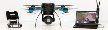
Figure 4 From left to right: drone manual controller (used only for take-off and landing); drone equipped with a RF payload; base station.
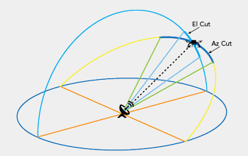
Figure 5 Process diagram with azimuth and elevation cut.
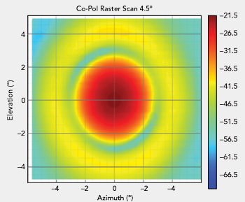
Figure 6 Graphical representation of a raster scan performed with the drone-based measurement method.
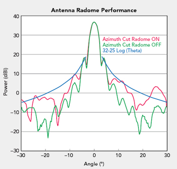
Figure 7 Analysis of a radome that has operated at sea for several years on a pattern cut.
Figure 4 illustrates the equipment, easily transported in a single case by a technician, needed for an antenna on-site test.
Setting up Before the Test: On-site base station set-up provides the reference position for the system, enabling the drone to know its exact location for performance of an accurate automated flight, and measurement of the antenna position with reference to the base station ensures that the antenna is at the center of all measurement flight paths. Preparation of the antenna under test (AUT) follows a specified step-by-step protocol, including the determination of Azimuth (Az) and Elevation (El) to ensure a clear line of sight (see Figure 5).
Aligning and Identifying the Antenna Pointing: Following on from finding the initial and approximate Az and El pointing of the antenna, the drone performs a raster scan measurement to correctly identify the exact Az and El angles, with further verification to ensure optimal accuracy.
Performing the Test: Guided in flight in real-time, the drone can take any desired measurements, taking an Az cut or Raster scan, changing frequency and signal amplitude. The first test results show the directivity of the antenna and shape of the radiation pattern. Measurement of actual antenna gain is achieved using different methods determined by the final desired measurement accuracy. As illustrated in Figure 5, a pattern cut is performed in a preprogrammed test route, with the drone following a flight path that maintains a constant distance between the AUT (based on the main beam Az and El) and each data collection point. Drone and received signal status are constantly monitored and results generated can be graphically plotted for visual inspection. Alternatively they can be provided in data format.
The essential antenna tests are:
- Principal cuts in Azimuth, with a span of ±20 degrees
- Principal cuts in Elevation, with a span of ± 10 degrees
- Raster scans, focusing on the vicinity of the main beam, at a span of ± 5 degrees both in Az and El, giving a highly visual 3D representation of the main beam
Figure 6 shows an example of such a measurement. All measurements are made in transmit and receive, and at three different frequencies (low, medium, high across the band) in both co- and cross-pol planes.
Drone testing conveniently enables antenna performance evaluation if the antenna is intended to operate with a radome. In such cases measurements with radome on and off are necessary. In Figure 7, the antenna will meet the SOMAP Requirement (blue line) without radome (green line). Meanwhile with the radome on (red line) it will not comply with SOMAP Requirements, this is due to the large energy displacement of the radome.
REVOLUTIONIZING DRONE TESTING SYSTEM
Drone testing is providing a reliable method of identifying the transmit and receive Co-polarization and Cross-polarization off-axis components of a satellite antenna. It is designed to meet the needs of testing ground antennas, specifically with respect to pointing accuracy, radiation patterns and how the radome performance affects the radiation diagram.
The QuadSAT system is designed for X- and Ku-Band with intention to expand to Ka-Band antenna testing. It provides flexibility in assigning power levels, frequency choices and polarization adjustment. The product will be released in more frequency bands, modulations and customizations.
The company is working closely together with leading satellite operators and GVF to make sure industry standards are met. At the same time, considering the growth of LEO and MEO constellations, a similar method for evaluating and verifying the performance of tracking algorithms is being developed.
Drone positioning anywhere with reference to the AUT with comparable datasets allows a manufacturer to compare the performance of a new antenna model with the performance of the same model of antenna which has been operating under a radome for a period of time.
Satellite operators are at times experiencing under-performing antennas operating in their networks. Antenna manufacturers cope with logistically difficult, time consuming and expensive testing procedures and service providers have no viable means to measure the changes in antenna performance over time. Under-performing terminals have the potential to cause interference, with transmitting antennas causing interference on adjacent satellites.
Existing test methods use a positioning system to rotate the AUT to measure the radiation pattern as a function of the rotation angle. In the new drone solution, the antenna is kept at its location while the test is performed. The drone is equipped with an RF payload and flies a preprogrammed test route based on the desired measurement plane. The position of the drone is recorded in real-time with high precision which is coupled with the measurements performed by a receiver at the antenna’s end.
Antennas operating in challenging environments are often covered by radomes for protection. These radomes must be manufactured for the frequency band of the antenna with great precision as even slight inaccuracies in the radome manufacturing process affects the performance of the antenna it covers. Exposure to the environment, such as sunlight, seawater, vibration, changing air pressure, or temperature, can change radome performance. The consequence can be antenna side-lobe degradation, beam deflection or depolarization, reducing the performance of the product combined of both radome and the antenna it covers.
The size and shape of radomes complicate testing at current test ranges because they often do not fit onto the test-bench where the antenna is installed. These restrictions might have particular implications if the AUT is located on a large mobile platform such as an aircraft, a ship, or is used in a high speed rail application. These limitations do not impact a drone-based test range where the drone moves around the antenna (with or without radome), allowing for improved test data on radome effect, improving accuracy in link analyses as well as detecting a degradation in radome performance.
For satellite operators, drone technology means being able to facilitate a wide variety of testing scenarios to control the performance and quality of satellite antennas before they are introduced into their network. For antenna manufacturers, drone technology means being able to perform antenna measurements in-house conducted by their research and development teams. For service providers, drone technology means being able to conduct tests in the field, on-site after new installations or maintenance to ensure that their service meets customer expectations. Service providers will also see a dramatic reduction in the cost of installation and maintenance for COTM, as they can test without the need to move a ship, an airplane, etc. to verify the installation. Ultimately, drone-based antenna performance testing will make testing much more cost-effective, flexible and less time consuming.
SUMMARY
As more satellites are launched into various orbits, the number of antennas on the ground will increase rapidly. The desire of users to have smaller and lighter antennas leads to more complexity of the individual system. This will make adequate antenna performance testing more important, as COTM designs differ substantially in their design, which results in the need for increased flexibility in testing methods.
A new industry tailored test method that consists of a drone, a base station, an RF payload and a receiver system has been developed. As the drone solution evolves in accordance with the industry’s needs, it will gradually eliminate the requirement to transport antennas to dedicated test ranges. The absence of size restrictions will accommodate antenna testing of a COTM system underneath its radome and thus provide valuable insight into its performance. This new drone solution will transform antenna performance measurement into a flexible, simple, quick and cost-effective method that has the potential to increase the overall quality of antenna terminals used in satellite communication, revolutionizing testing in this industry.
Reference
- Northern Sky Research, “COVID-19 Impact Survey Results: Satellite & Space,” April 2020, https://www.nsr.com/wp-content/uploads/2020/04/NSR-April-2020-COVID19-Survey-Results.pdf.