
A dual frequency, active retrodirective array for wideband wireless charging of portable devices uses a wideband circularly polarized microstrip patch antenna array with sequential rotation and surface wave suppression. The retrodirective array operates at 2.4 GHz for the interrogating signal and over a wide band (5.8 to 6 GHz) for the retransmitted signal using up-converting mixers. Beam scanning inherent in retrodirective arrays ensures a constant power level available to the charging devices, regardless of location over a 50 degree angular sector of retrodirectivity.
Wireless power transfer (WPT) for charging electronic devices has been a focus of recent research.1-6 The most popular method is near field, which is based on magnetic field induction between two coils placed in close proximity to each other over a short distance.7-9 Wireless power transfer using microwaves overcomes the distance limitation of induction coupling and avoids the shortcomings of laser techniques.10-13 An example of microwave power transfer using a monopole with a corner reflector was demonstrated by Abbasi et al.14
A retrodirective array is a smart antenna array that scans its main beam to point to the direction of a transmitter without prior knowledge of the transmitter’s location. For WPT, this ensures that all devices within a sector receive uniform power density, unlike antennas with fixed beams. A two-dimensional Van Atta array for far-field WPT systems15 used a wide angle slot antenna to realize wideband performance. A multi path retrodirective technique was studied by Sasaki and N. Shinohara16 for WPT. Dual frequency retrodirective arrays can also be used for bidirectional communication transmission and reception.17, 18 Li and Jandhyala,19 investigated the performance of Van Atta retrodirective arrays assuming dipole antennas as array elements.
Conventional microstrip antennas printed on dielectric substrates suffer from excitation of undesired surface waves. In addition to lowering antenna efficiency and distorting radiation patterns, surface waves increase the mutual coupling between elements, which can lead to scan blindness. This is a problem in retrodirective arrays since the antenna beam is scanned to point toward the interrogating signal. Shorting pins are often used to increase efficiency and reduce mutual coupling.20, 21
To increase the axial ratio and impedance bandwidth of circularly polarized arrays, sequential rotation techniques can be used.22-24 Fairouz and Saed25 used sequential rotation, where the four elements in the subarray are rotated by 90 degrees in orientation and the input ports are excited with a uniform magnitude and 0, 90, 180 and 270 degrees of phase difference.
For this work, a wideband retrodirective array uses a circularly polarized sequential rotation technique in the transmitting antenna. The transmitting array consist of four microstrip patch elements modified by adding four shorting pins to reduce surface wave excitation. This minimizes mutual coupling between array elements, for higher gain, better radiation patterns and improved beam scanning (by avoiding scan blindness). Circular polarization is chosen for the wireless charging application to ensure devices receive the transmitted signal (the charging signal) regardless of orientation. The device’s data signal (e.g., Wi-Fi) can be used as the interrogating signal that the retrodirective array uses to direct its transmitted beam toward the wireless device for charging. We chose 2.4 GHz as the frequency of the interrogating signal and a wideband frequency range (from 5.8 to 6 GHz) as the transmitted signal.
System Design
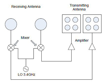
Figure 1 Wideband retrodirective array system.
The system block diagram is shown in Figure 1. The transmitting antenna array at 5.8 to 6 GHz is a 2 x 2 microstrip array with sequential rotation and surface wave suppression. The subarrays are aperture-coupled to a feed network on another substrate in a two-layer configuration. The receiving array consists of two conventional microstrip patch antennas at 2.4 GHz. The 2.4 GHz interrogating signal is mixed with a local oscillator (LO) signal in an up-converting mixer to produce 5.8 to 6 GHz for transmission.
This design differs from conventional phase conjugating retrodirective arrays, even though both use mixers. In conventional designs, the mixers are used as downconverters requiring a high LO frequency (equal to the sum of the RF and IF frequencies); therefore, down-conversion results in phase conjugation of the retrodirective signal. In this design, the mixers are used as upconverters, and therefore do not produce phase conjugation. The advantage is that a lower LO frequency is used, equal to the difference between the RF and IF frequencies.
Retrodirectivity is achieved by properly connecting the receiving and transmitting arrays to scan the transmitter beam in the direction of the interrogating signal, as in a Van Atta array. Since the transmit and receive frequencies are different, it is very important to properly choose transmission line lengths in the feed network, as well as transmit and receive array element spacings, to avoid beam pointing errors. The transmission line lengths between the receiving array elements and the mixers must be equal, and the transmission line lengths connecting the mixers to the transmitting array elements must also be equal. This ensures that phase shifts due to the connecting lines are equal for each transmit-receive antenna pair. Two amplifiers are used before the transmitting array to increase the transmitted power.
The circularly polarized microstrip patch antenna used in the transmitting subarrays is designed to suppress surface waves by incorporating four shorting pins. The positions of the shorting pins are determined by numerically solving the following:12

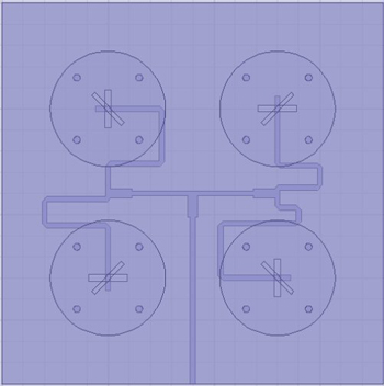
Figure 2 Two-layer, 2 x 2 sequentially rotated antenna array.
The transmitting array uses a circularly polarized microstrip patch as the array element. Each element employs a diagonal slot to obtain circular polarization. Aperture coupling, employing rectangular slots in the ground plane, feeds the antenna subarray from a network on another substrate (see Figure 2). Sequential rotation of the 2 x 2 subarrays improves axial ratio bandwidth. The feed network uses T-junction power dividers with appropriate characteristic impedances and line lengths to obtain the necessary phase shifts. The substrate used for the feed network is RT/Duroid 6010 with a dielectric constant ετ = 10.2 and thickness of 1.27 mm. The antenna substrate is RT/Duroid 5870 with a dielectric constant ετ = 2.33 and thickness of 1.575 mm. The complete array is simulated and optimized in ANSYS HFSS.25p
MEASUREMENTS
A monostatic setup used to test the performance of the retrodirective system is shown in Figure 3. A 2.4 GHz transmitter and a 5.8 to 6 GHz receiving antenna are collocated on a fixed platform while the retrodirective system is mounted on a rotational stage. The radiation pattern recorded by the receiving antenna measures the system’s ability to steer its beam toward the transmitter. The measurement is then repeated, for comparison, using a normal non-retrodirective array.
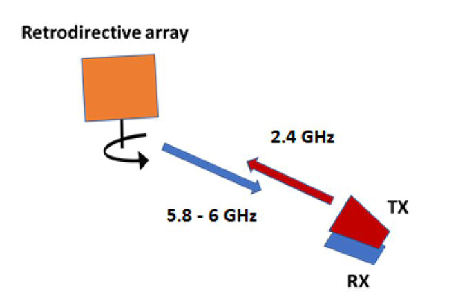
Figure 3 Retrodirective array test setup.