
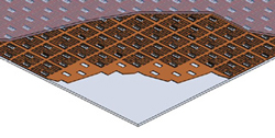
Figure 4 LC-based phased array, where each radiator is fed with an independent phase shifter.
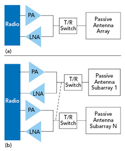
Figure 5 Fully analog beam steering array (a) and hybrid beam steering (b) architectures.
The LC technology is passive and biasing, using very low power. Controlling up to 512 radiating elements consumes less than 0.5 W. Depending on topology and design choices, an insertion loss of 2 to 3 dB is achieved and the beam steering time is in milliseconds.6 This steering time is longer than that of an array using beamformer ICs, which might seem to be a limitation; however, a steering time on the order of a few milliseconds is compatible with a latency of a 1 ms or less. Latency is the time between a stimulation and the corresponding response, which is mainly a signal processing issue, while the steering time is the time necessary to change the direction of a beam.
Fast steering is required for two main scenarios: one is for tracking high-speed vehicles such as trains and airplanes, which is achievable with LC technology.7 The second is for optimal resource allocation when the antenna is used as a macro base station and schedules/switches between different users, on the order of symbol/slot durations similar to sub-6 GHz macro base stations. Operating at mmWave, however, the base station antenna is used mainly as a small cell hotspot or FWA access point, where the number of users is less and fast switching is not necessary.
Other LC-based antennas based on holographic beamforming use LCs in a metamaterial approach within leaky wave antennas. These are based on resonant meta-atoms and suffer from fundamental limitations, such as limited bandwidth. These solutions require tens of thousands of elements, equivalently meta-atoms, to interface with mating structures,8 and they have complex design and control schemes.9 In application, several thousand tunable devices must be controlled, which is a hurdle to scale antenna size and reduce cost.
ANTENNA ARCHITECTURES FOR 5G APPLICATIONS
Two antenna solutions are possible depending on the application and type of link: (1) fully analog beam steering antenna arrays for point-to-point (PtP) links and (2) hybrid analog/digital beam steering antenna arrays with multi-beam capability for point-to-multipoint (PtMP) links, such as massive MIMO (mMIMO) base stations (see Figure 5). In the hybrid architecture, one RF chain is used for each subarray; in the analog architecture, a single RF chain is used for the entire array. The RF chain (RF front-end) comprises of one power amplifier (PA), one low noise amplifier (LNA) and a T/R switch meeting the 5G power levels and TDD requirements.
The fully analog architecture shown in Figure 5a is suitable for single beam (single user, PtP) cases and offers the best cost and simplicity. For PtMP scenarios, the architecture in Figure 5b provides the best trade-off between beamforming flexibility and RF front-end cost and complexity. Compared to silicon-based beamforming antennas, the LC smart antenna and its hybrid beamforming architecture require fewer RF components. Using LC phase shifter technology to achieve the phase shift for each element with the passive subarrays is a much lower cost and consumes less power compared to a typical MMIC approach. The beamforming architecture does not require an LNA, PA and T/R switch for every element, rather one per subarray.
MMIC-based phased arrays typically use off-the-shelf beamforming ICs available from companies such as Analog Devices, Anokiwave and Qorvo. An 8 x 8 antenna using one of those commercial ICs consumes around 20 W compared to only 5.5 W for the LC antenna solution. Table 1 compares the performance of an ALCAN 8 x 8 array with a single beam analog architecture compared to several silicon MMIC-based 8 x 8 arrays, assuming operating at 28 GHz.
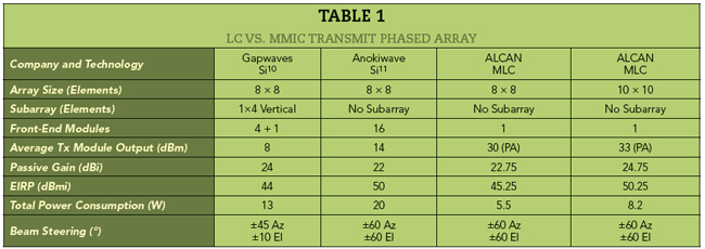
The differences become more significant for larger arrays, especially power consumption, because the power consumption of the LC solution does not increase linearly with an increasing number of array elements. For example, for a 16 x 16 element array with four beams and a minimum equivalent isotropically radiated power (EIRP) of 60 dBm, the LC antenna’s overall power consumption is around 19 W, compared to 65 W for antenna arrays based on silicon-based ICs.11
In a simplified case12 for a random Dallas suburb with 800 houses per square kilometer, nine cell sites with inter-site distance of 500 m are required to ensure 1 Gbps service per user. Each cell site requires at least three access antennas with 120 degree coverage to provide full 360 degree coverage around the cell, leading to a minimum of 27 access antennas per square kilometer. The maximum authorized EIRP for an outdoor base station access antenna is 75 dBm, and operators tend to use this maximum level to ensure the highest coverage and capacity.13 For silicon MMIC-based solutions, an antenna with an EIRP of 75 dBm consumes more than 200 W, while the LC antenna only consumes around 35 W and can be powered by a solar panel with an aperture of 48 x 66 cm.
LC-based antennas benefit from a cost-efficient phase shifting technology that leverages the existing mass production capabilities of LCD production lines with a low marginal cost of producing an additional type of LC panel. This economy of scale enables ALCAN to reduce LC phase shifter cost by 100x, to around $300/m2, compared to semiconductor phase shifters, which are estimated to cost around $30,000/m2 using 30 cm diameter wafers. Depending on the antenna application, LC-based phased array antennas - including the RF front-end with a PA, LNA and T/R switch for each array or subarray - consume up to 5x less power and are up to 10x lower cost compared to semiconductor-based phased array antennas, especially at mmWave frequencies.
APPLICATIONS
A terrestrial mobile network (see Figure 6) generally uses two types of links: PtP and PtMP. PtP links provide backhaul and fronthaul connections between the macros and small cells, and they mainly employ high gain antennas with narrow beam widths. PtP links require beam steering for aligning the antennas during installation of the link, dynamic alignment to compensate for antenna twisting and swaying and network reconfiguration.
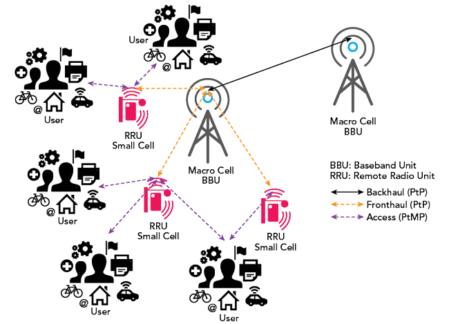
Figure 6 Notional 5G heterogeneous network.14
A PtMP link is used to connect between the base station and several simultaneous users, providing them with access to the network and the internet. Here, wider beams are required than with PtP links, to handle beam steering scenarios such as following on-the-move users until a handoff to a neighboring node or auto-aligning the link to establish FWA service between the base station and customer premises equipment. Antenna solutions with multiple beams are increasingly deployed to increase access capacity via MIMO arrays.
A new trend called self-backhauling or “integrated access and backhaul,” uses a single antenna to form both PtP and PtMP links. For such use cases, modular mMIMO antennas with hybrid beamforming architectures seem to offer the best, most compatible, solutions. ESAs are also required at the user equipment (UE), especially at mmWave frequencies to overcome path losses. UEs need high gain antennas and narrow beams, and beam steering is required to align the UE’s narrow beam with the access point’s beam, and the system must maintain alignment if the UE is moving, e.g., CV2X between the base station and a vehicle.
CONCLUSION
For 5G, ESAs are becoming a basic requirement both for network nodes and UEs. At mmWave, where they will be deployed in large numbers, they must be small in size, to be unobtrusive in urban areas; be low-cost, to be economically justifiable; be energy efficient, to consume minimal power; and have low mass, to ease installation and maintenance.
The main features that differentiate LC-based phased arrays from other antenna solutions are 1) energy efficiency, with low power consumption (a few watts) and little heat dissipation; and 2) low-cost compared to traditional active phased array antennas, because they do not use MMIC-based phased shifters. LC phased arrays are a “pure” passive solution with continuous beam steering.
Depending on the application, LC-based phased arrays support beamforming architectures that are either fully analog, for single beam ESAs, or hybrid analog/digital, for multi-beam ESAs. They have response times of milliseconds, which are compatible with a 1 ms latency requirement for most 5G use cases, such as small cells, FWA and UE. LC-based arrays are extremely flat, compatible with low profile applications.n
Acknowledgment
The authors would like to thank Professor Rolf Jakoby, Institut für Mikrowellentechnik und Photonik (IMP) at Technische Universität Darmstadt, and André Doll, 5G antenna senior advisor and former CTO of RFS, for their valuable contributions to this article. We also extend our gratitude to the IMP labs at TUDA for their test facilities.
References
- “WRC-19 Identifies Additional Frequency Bands for 5G,” ITI News, November 2019, Web. news.itu.int/wrc-19-agrees-to-identify-new-frequency-bands-for-5g/.
- F. Pujol, C. Manero and S. Remis, “5G Observatory Quarterly Report 5,” European Commission DG Communications Networks, October 2019.
- C. Weickhmann et al., “A Low-Cost, Flat, Electronically Steerable Array Antenna for New Massive NGEO Constellations Ground Terminals and Future 5G,” EuCAP, April 2019, Krakow, Poland.
- F. Goelden, A. Gaebler, M. Goebel, A. Manabe, S. Mueller and R. Jakoby, “Tunable Liquid Crystal Phase Shifter for Microwave Frequencies,” Electronics Letters, Vol. 45, No. 13, June 2009, pp. 686–687.
- R. Jakoby, O. H. Karabey and W. Hu, “Phase Shift Device,” U.S. Patent 10141620, issued November 27, 2018.
- F. Goelden, A. Gaebler, S. Mueller, A. Lapanik, W. Haase and R. Jakoby, “Liquid-Crystal Varactors with Fast Switching Times for Microwave Applications,” Electronics Letters, Vol. 44, March 2008, pp. 480–481.
- R. E. Hattachi and J. Erfanian “NGMN 5G White Paper,” NGMN Alliance, February 2015.
- M. C. Johnson, S. L. Brunton, N. B. Kundtz and J. N. Kutz, “Sidelobe Canceling for Reconfigurable Holographic Metamaterial Antenna,” IEEE Transactions on Antennas and Propagation, Vol. 63, No. 4, February 2015, pp. 1881-1886.
- A. Bhattacharya, “Modeling Metamaterials - Metamaterial Development using Electromagnetic Simulation,” Physics’ Best, April 2014, pp. 30–32.
- C. Bencivenni, T. Emanuelsson and M. Gustafsson, “Gapwaves Platform Integrates 5G mmWave Arrays” Microwave Journal, Vol. 62, No. 2, February 2019, pp. 22–38.
- “Introduction to All Silicon Millimeter-Wave 5G Arrays,” Anokiwave Inc., March 2019, Web. www.anokiwave.com/contact/overview_request/mmWave_array_wp_request.php.
- B. Peterson, “RF Front-end Technology and Tradeoffs for 5G mmWave Fixed Wireless Access,” Microwave Journal, Vol. 61, No. 11, November 2018.
- “Use of Spectrum Bands Above 24 GHz for Mobile Radio Services, In the matter of GN Docket No. 14-177, IB Docket No. 15-256, RM-11664, WT Docket No. 10-112, IB Docket No. 97-95,” Federal Communications Commission, July 2016, Retrieved from mentor.ieee.org/802.18/dcn/16/18-16-0058-00-0000-fcc-mmwave-r-o-and-fnprm.pdf
- M. R. D. Kodnoeih, Development of Next-Generation 5G Directive Antennas at Millimeter Waves, PhD thesis, UNIVERSITE DE NANTES, France, 2018.