
Electronically steerable antennas (ESA) are key components for 5G, especially at mmWave frequencies. Typical ESAs are phased arrays based on silicon beamforming integrated circuits (IC). Notwithstanding the flexibility silicon-based ESAs offer, two potential obstacles to widespread deployment are power consumption and equipment cost. These result in high operating and capital expenses for network operators. As an alternative to silicon-based active phased arrays, liquid crystal (LC)-based passive phased arrays are being introduced for 5G applications.
5G is being deployed worldwide using both sub-6 GHz (e.g., Deutsche Telekom, O2, Sprint, Vodafone and Three) and mmWave (e.g., AT&T, Verizon and SK Telekom) frequency ranges. This fifth generation will be a mobile network and, unlike its predecessors (4G, 3G and 2G), it aims to be an “everything network,” i.e., available “everywhere” for “everyone,” able to provide high data rates with low power consumption.
One of the key hardware components of the physical layer is the antenna. Until now, typical antenna solutions have been either parabolic antennas for high gain links (e.g., point-to-point backhaul) or sectorial antennas for base stations (e.g., point-to-multipoint). These antennas offer no beam steering features for backhaul or only a few degrees in just one dimension (1D), for base station vertical tilting. For 5G, ESAs are required, especially at mmWave frequencies.
5G ANTENNA REQUIREMENTS
5G frequency bands are divided into sub-6 GHz and mmWave (i.e., greater than 24 GHz). Because of their propagation properties, the sub-6 GHz range is more suitable for larger, less dense cells in rural areas. For these cases, 1D antenna steering (e.g., azimuth) might be adequate.
5G offers highly reliable networks with high data rate services. High data rates require large bandwidths available at higher frequencies, such as mmWaves. This is underscored by a recent announcement by the International Radio Union (ITU) after World Radiocommunication Conference 2019 (WRC-19). Five additional mmWave frequency bands (4.25 to 27.5, 37 to 43.5, 45.5 to 47, 47.2 to 48.2 and 66 to 71 GHz) are identified to facilitate diverse 5G usage scenarios.1 Recent frequency band auctions in the U.S., Japan and the European Union allocating the 26 GHz band for 5G and early 5G deployments at mmWave frequencies in the U.S. and Asia demonstrate increased interest in mmWaves for applications such as fixed wireless access (FWA) and 5G hot spots within the 5G cellular network.2
Urban areas with high mobile traffic, i.e., with a high demand for capacity per subscriber and large numbers of subscribers, require high data rates - hence, large bandwidth. This leads inevitably to increasing frequencies up to mmWave, where large swaths of frequency spectrum are available. Due to high path losses at these frequencies and because of high mobile traffic, an (ultra) dense cellular network with many pico- and femtocells must be deployed to serve many users with high throughput. To reduce the impact of mmWave path loss and to reduce interference in these dense cellular networks, narrow beamwidth high gain antennas with 2D beam steering or beamforming and multi-beam capabilities are required.
LC-BASED PHASED ARRAY
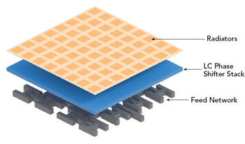
Figure 1 LC-based phased array.
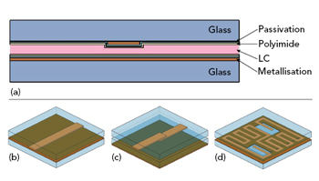
Figure 2 LC phase shifter stack: cross-section (a), IMSL (b), loaded line (c) and layout with input and output (d).
As previously detailed by Christian Weickhmann et al.,3 LC antenna technology combines liquid crystal display (LCD) technology with microwave LCs and array antenna design (see Figure 1). The phased array consists of a feed network, an LC phase shifter stack and a radiator stack. Using this approach, all parts can be designed independently and in a modular fashion. The LC phase shifter stack is fabricated using standard LCD processes. This allows for large-scale fabrication accommodating virtually any aperture size, including segments or antenna groups. The LC phase shifter stack consists of two glass sheets separated by spacers, where the LC material is filled in between. Depending on the chosen device topology, the LC layer thickness may vary from a few to tens of micrometers. An inverted microstrip line (IMSL) implements the phase shifting functionality, as shown in Figure 2, with the typical LC layer thickness of the IMSL approximately 100 μm. Other phase shifter topologies with LC layer thicknesses of just a few micrometers enable lower loss and more compact size,4,5 essential to reduce response time to milliseconds.6
In the LC phase shifter stack, the inner surfaces of the glass layers are metallized and then coated with a polyimide (PI) layer to anchor the LC and enforce an orientation of the material. Usually, the RF signal, due to its polarization, experiences low effective permittivity. When a voltage is applied between ground and signal, the LC reorients according to the magnitude of the applied voltage (see Figure 3). If the applied bias voltage (Vb) is higher than a threshold voltage (Vth), the molecules tend to orient toward the applied electrostatic field. The resultant orientation is determined by the equilibrium between the applied electrical force and elastic force in the bulk LC, due to the alignment layer. Hence, continuous tunability of the LC material is possible. The more the LC orients along the bias field, the higher the effective permittivity for the traversing RF signal. When the bias voltage is turned off, the molecules align back to the initial orientation because of the alignment layer. Other topologies are possible, which offer more design choices, but the operating principle is the same.
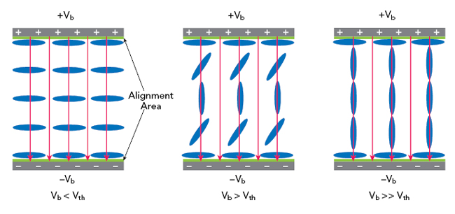
Figure 3 Tuning the LC phase shifter.
A top view of an LC-based array (see Figure 4) shows each unit cell has independent phase shifters. Hence, when they are fed from a feed network on one side and coupled into radiating elements on the other side, a classic phased array is formed, where each individual radiator has its corresponding independent phase shifter. The phase shifters can achieve any phase value, enabling continuous beam steering, unlike a semiconductor digital phase shifter. Various panel sizes are possible: TV-screen apertures for satellite reception, CD-sized panels for conformal layouts or multi-antenna modules for terrestrial applications like 5G. ALCAN has developed and patented a low-cost electronics solution developed exclusively for phased arrays.