
Technical Feature
A New Type of Amplitude Equalizer for In-band Flatness Improvement
There is a growing need in modern communication systems for low cost bandpass filters of small size, high selectivity and flat passband response in order to meet the demands for inter-channel power balance, and to avoid interference. Due to the limited Q values of small size resonators, bandpass filters suffer from relatively large ripples at the band edges especially when the order of the filter is increased to meet the need for high selectivity. A new cascade type of amplitude equalizer is proposed to compensate for the large ripples while maintaining high selectivity. The cascaded equalizer consists of a two-pole bandpass filter and matching blocks at the input and output. Its amplitude characteristic is the inverse of the bandpass filter or system response to be compensated. A nine-pole bandpass filter with 8 MHz bandwidth and 3.3 dB passband ripple was improved to less than 1 dB ripple with additional selectivity using this configuration.
Hee-Yong Hwang and Sang-Won Yun
Sogang University
Seoul, Korea
Joong-Sung Chung
Amotech Co.
Seoul, Korea
Recently, various communication systems such as AMPS, GSM, PCS, GPS, IMT-2000, WILL, B-WLL and LMDS have been fully developed or widely used. The improvement of system performance with small size and low cost components is driven by the expansion of the market and the development of new technologies for these systems.1,2
Bandpass filters are one of the critical components in most communication systems. They are used to isolate a channel or a band from adjacent ones while maintaining a compact size. In the design of bandpass filters, one of the main issues is how to realize a high performance filter, with close to ideal characteristics, that features small size and low cost. As the size of the filter is reduced, the flatness in the passband of the filter is, inherently, degraded due to the lowered Q factors of the resonators.
The degradation of the filter performance is more serious as the number of poles increases when the bandwidth is small and a very tight skirt frequency specification is imposed. This problem can be solved by adding an amplitude equalizer to the bandpass filter or by inserting it into a proper position in the system. The equalizer is also a filter that compensates the passband shape of a normal bandpass filter. The shape of the frequency response in the passband is designed as the inverse or concave shape compared to the normal one, and it compensates for the convex shape of the normal bandpass filter. One reflection type equalizer, called a "hybrid coupled amplitude equalizer," was proposed by R. Snyder.3 However, for the reflection type amplitude equalizer, a 90° hybrid and two identical stubs or two rejection filters must be used to solve the port matching problem and to provide the required complementary function.
In this article, a new, cascade type amplitude equalizer is proposed that has only one two-pole bandpass filter for the complementary function. Using buffer amplifiers or simple attenuation pads solves the matching problem. An additional advantage is the improvement in skirt response by as much as the number of poles used in the RF amplitude equalizer.4 The design method and an application example of the amplitude equalizer in cellular band are presented. The designed amplitude equalizer properly and easily compensates the degraded shape of the passband characteristics of the bandpass filter. As a result, a small sized filter can give the same good frequency response as a large bandpass filter made of higher Q and larger resonators. This amplitude equalizer can also be applied to the design of various communication systems in which improved passband flatness is required with a limited size, in order to maintain uniform characteristics throughout the whole communication channels.
Fig. 1 Flatness degradation for various resonator Qs.
Amplitude Equalizer
The passband frequency response of a conventional bandpass filter made with resonators of finite quality factor is shown in Figure 1 . In general, as the size is reduced, the quality factor decreases and the flatness degradation L or the passband ripple DS increases. The comparison is made by using a seven-pole Chebyshev bandpass filter (BPF) with a bandwidth of 10 MHz (1 percent) and a center frequency of 1 GHz. The designed passband ripple is 0.01 dB (Qu = ∞, L = 0.01 dB). If small resonators with Qu (unloaded quality factor) of 500 are used, the flatness degradation is approximately 5.2 dB. This situation is the same when a BPF is designed with a smaller fractional bandwidth and/or a larger number of poles. Because of this phenomenon, the passband ripple and skirt characteristics of a realizable BPF using resonators of limited size cannot often meet a given BPF specification. As the number of resonators used in the filter to achieve a sharp skirt response increases, the passband ripple DS also increases. Therefore, depending on the passband flatness specification in a BPF or system, the proper size of the resonator must be chosen to have a sufficient quality factor.
Fig. 2 Typical frequency response of a bandpass filter or system.
Fig. 3 Desired characteristics of the amplitude equalizer.
Fig. 4 Response of a bandpass filter compensated by an amplitude equalizer.
Figure 2 shows a typical frequency response for a bandpass filter or system to be considered. The passband ripple shape can either be calculated numerically or measured experimentally. Then, a two-pole bandpass filter can be designed that has the inverse ripple shape, as shown in Figure 3 . By cascading the two filters, an ideal filter can be approached, where the passband ripple is nearly removed, as shown in Figure 4 . The amplitude equalizer is designed as a bandpass filter of any number of poles according to the amplitude shape of the BPF or system to be compensated. The standard BPF configuration shown in Figure 5 5 and circuit simulation tools such as ADS or MDS are used to design the equalizer with the proper ripple DS and the fractional bandwidth, W, by comparing the bandwidths of the original filter and the equalizer. The simplest amplitude equalizer is a two-pole BPF that has the same ripple as the normal BPF but with an inverse passband shape. The passband ripple of the normal filter and that of the amplitude equalizer should be equal.
DS = DSe (1)
where DS and DSe are the ripple of the normal filter or the system under consideration, and that of the amplitude equalizer, respectively.
The following equations are used to design the two-pole equalizer
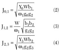
where
Jij = J-inverter values
gi = element values of the low pass prototype filter
w1 = cut-off frequency of the low pass prototype filter
Fig. 5 A bandpass filter with admittance inverters.
The entire block diagram of the amplitude equalizer is shown in Figure 6 . It consists of a shaping filter that has an inverse passband response, and one or two buffer amplifier(s) and/or attenuator(s) that meet the matching condition at the input and output ports. The shaping filter cannot be normally matched to 50W because of the large ripple, which means a passband mismatching condition. The gain block or attenuation block is used for solving the mismatching problem. A 10 dB attenuator results in a return loss of 20 dB, when used in the configurations shown previously.
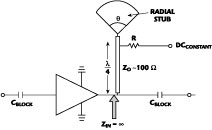
Fig. 6 Block diagrams of various amplitude equalizers.
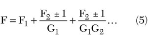
The noise figure of the amplitude equalizer can be minimized by the gain of the buffer amplifier in the input stage, because the loss term of the shaping filter and attenuator is divided by the gain G of the amplifier. The amplitude equalizer is cascaded either before or after the bandpass filter or the system to be compensated according to the filter or system requirements such as noise figure, gain and matching conditions. The configuration using only attenuators must be inserted after a gain block in order to avoid the noise figure problem that would result when the attenuator is used at the input. The total noise figure of the cascaded blocks is given by6
Amplitude Equalizer Example
A nine-pole BPF was designed using ceramic coaxial resonators with dimensions of 6 x 6 mm. The filter has an 840 MHz center frequency, 8 MHz bandwidth, 6.8 dB insertion loss and Qu = 550. Figure 7 shows a large flatness degradation equal to 3.3 dB due to the small size resonators and hence the small Qu s. This filter doesn't meet the required passband flatness for the indoor repeater of the cellular system of Korea.
Fig. 7 Measured response of the 840 MHz bandpass filter.
If an improved passband flatness, by 1 or 2 dB depending on the repeater systems is desired, much larger resonators, with a minimum Qu of 2000, must be used. Actually, this Qu value is difficult to obtain from ceramic coaxial resonators.
The amplitude equalizer used a configuration composed of a matching/gain section, a shaping filter and a matching/attenuator section. The three blocks of the amplitude equalizer are shown in Figures 8 , 9 and 10 .
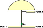
Fig. 8 Matching and gain block for the amplitude equalizer.
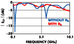
Fig. 9 Shaping filter block for the amplitude equalizer.
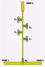
Fig. 10 Matching and attenuation block for the amplitude equalizer.
The INA02186 FET is biased at Id = 35 mA, and the input port is connected to the nine-pole BPF. Cb is a DC-blocking capacitor. The bias circuit consists of an RF choke coil (RFC), RF bypassing capacitor (Cc ) and RD . L1 , C1 , L2 and C2 of the matching and gain block are used for input and output matching of the block. The input of the shaping filter block is matched to the FET by the matching circuit composed of L2 and C2 of the matching and gain block. The amplifier should be designed properly, depending on the required specification for noise figure and IMD required by the system. The output of the shaping filter is matched to 50W through the attenuator. A 15 dB attenuator providing a -30 dB return loss to the amplitude equalizer output was designed. Actually, a 10 dB attenuator is sufficient for many systems, which gives a -20 dB return loss.
The attenuator is designed using Equations 6 and 77
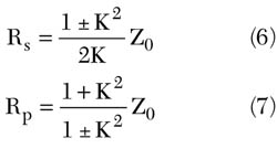
where
K = power attenuation
Z0 = load impedance
The two-pole shaping filter is constructed using ceramic coaxial resonators. The two resonators, with dimensions of 6 x 6 mm, are coupled through a small rectangular window so that the shaping filter can have a 3.5 dB passband ripple. The simulated and measured responses are compared in Figure 11 and agree well with each other. It was simulated linearly using S2P data at Id = 35 mA from the vendor. After connecting the amplitude equalizer to the nine-pole bandpass filter, the resulting passband ripple is reduced to less than 1.0 dB compared to 3.3 dB without the equalizer, as shown in Figure 12 . To achieve the same results without the amplitude equalizer, large resonators that have Qu greater than 4000 would have to be used such as the ones used in the basestation. The measured noise figure of the amplitude equalizer was 4 ±0.3 dB with the INA02186 device. It mostly depends on the transistor or MMIC used in the matching and gain block.
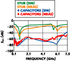
Fig. 11 Simulated and measured responses of the amplitude equalizer.
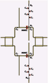
Fig. 12 Filter response with an without the amplitude equalizer.
Conclusion
A proposed cascade amplitude equalizer is presented for improving the performance of a bandpass filter frequency response used in cellular band. Generally, it is very difficult to make a bandpass filter that satisfies all the requirements of small size, sharp skirt response and passband flatness simultaneously. The proposed amplitude equalizer offers one solution to this problem. It consists of a shaping filter, and input and output matching blocks.
By using the proposed amplitude equalizer, the 3.3 dB ripple of a nine-pole BPF in the cellular band is improved to be less than 1 dB and the skirt response is also improved by the shaping filter. Therefore, a small size filter with the proposed amplitude equalizer gives an even better frequency response than that of a bigger filter without the amplitude equalizer. Using resonators with a Qu of 550, a BPF was obtained that has the same flatness as a filter with resonators Qu s in the thousands. This amplitude equalizer can be used not only for bandpass filters but also for many communication systems where reduced size and improved in-band flatness are required.
Acknowledgment
The authors would like to thank Y.J. Kim, D.H. Lee, U.T. Lee of Amotech Co., M.J. Kim of Samsung and M. EL Sabbagh of UMCP for their helpful assistance.
References
1. K. Wakino, T. Nishikawa and Y. Ishikawa, "Miniaturization Technologies of Dielectric Resonator Filters for Mobile Communications," IEEE Transactions on Microwave Theory and Techniques , Vol. 42, No. 7, July 1994, pp. 1295-1300.
2. J.P. Simmons Jr., "Practical HTS/Cryogenic Systems for Wireless Applications," Microwave Journal , Vol. 39, No. 10, October 1996, pp. 124-136.
3. R.V. Snyder, "Lossy, Hybrid Coupled Amplitude Equalizers for Narrow Band Filters," IEEE MTT-S Symposium Digest , 1984, pp. 205-211.
4. H.Y. Hwang, J.S. Jung and S.W. Yun, "An RF Amplitude Equalizer Improved Shape Factor of Bandpass Filter," The Journal of Korea Electromagnetic Engineering Society , Vol. 1, No. 1, May 2001, pp. 83-87.
5. G. Matthaei, et. al., Microwave Filters, Impedance-matching Networks and Coupling Structures , Artech House Inc., Norwood, MA, 1980.
6. G. Gonzalez, Microwave Transistor Amplifiers Analysis and Design , Second Edition, Prentice Hall, 1997.
7. R.E. Collin, Foundations for Microwave Engineering , McGraw Hill Inc., 1992, pp. 400-402.
Hee-Yong Hwang received his BS degrees in biology and electronic engineering from Seoul National University in 1988 and 1992, respectively, and his MS and PhD degrees in electronic engineering from Sogang University, Seoul, South Korea, in 1995 and 1999, respectively. From March 2000 to February 2001, he was with the department of electronic engineering at Sogang University as a tenured professor. He is currently with the department of ECE, University of Maryland, as a visiting researcher. He is also a research adviser for Amotech Co. His research interests include microwave passive and active filters, and RF systems.
Sang-Won Yun received his BS and MS degrees in electronic engineering from Seoul National University in 1977 and 1979, respectively, and his PhD degree in electrical engineering from the University of Texas at Austin in 1984. Since September 1984, he has been with the department of electronics engineering at Sogang University, Seoul, South Korea, where he is a full professor. Since January 1999, he has been serving as a Korea MTT chapter chairman. His research interests include microwave and millimeter-wave devices and circuits.
Joong-Sung Chung received his BS, MS and PhD degrees in electrical engineering from Sogang University, Seoul, South Korea, in 1984, 1987 and 1996, respectively. From 1987 to 1990, he was with the Agency for Defense Development as a researcher. Since 1997, he has been with Amotech Co. as a microwave component development engineer. His current interests are ceramic devices in microwave applications.