
The result of these phenomena is greater insertion loss through transmission lines, greater attenuation in connectors, poorer match between interconnects and less tolerance to misalignment in the connections between transmission lines. This is why, in many cases, waveguide interconnects are necessary for mmWave applications, as losses and mismatches are considerably less in waveguide compared to coaxial transmission media. It is also important to minimize transmission line lengths by placing the ATE system as close to the device under test (DUT) as possible.
For the final few centimeters at mmWave frequencies microstrip/stripline transmission lines are often used with IC load boards. Waveguide, although superior electrically, can suffer from its own mechanical issues. It is rigid and has physically large interconnects. For example, the UG387/u flange typically used between 60 and 90 GHz has a diameter of almost 20 mm. Some devices can have up to 24 mmWave ports on a single component. Physically routing waveguide through the interface layer for 24 ports can represent an impossible task. Several manufacturers are creating custom small interface flanges to address the flange issue. Proprietary waveguide technology that is both thin-walled and conformable has also been developed that minimizes the routing challenges without sacrificing high frequency performance characteristics. Figure 2b illustrates a modular test system with a configurable mixed signal interface. Figure 3 is a close-up view of the mixed signal interconnects.
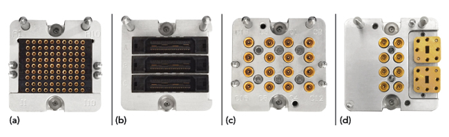
Figure 3 Modular interfaces for mixed-domain power (a), digital (b), RF/analog (c) and mmWave (d).
Vector-Based Measurements for Accurate mmWave Calibration
The frequency dependent degradation in performance that emerges at higher frequencies also impacts test system architecture and calibration. Testing accuracy depends on ensuring that the calibration plane is extended to the DUT plane, i.e. the behavior of the interconnects and associated parasitics are part of the test environment.3,4
In production there is always interface hardware between the test instrument and the DUT. This may be as simple as a cable or waveguide or might include multiple active components. For accurate measurements, the hardware must be calibrated. At lower frequencies, it is often acceptable to calibrate only to the instrument interface. At mmWave frequencies, however, it is extremely difficult to achieve acceptable test results without calibration to the DUT. This requires on-wafer or in-socket standards, typically open/short/load and a vector measurement system to effectively de-embed test results from the testing environment.
In addition to individual instrument calibration, mmWave ATE must also include vector calibration of the interface layer and the ability to combine the calibration layers into a cohesive overall calibration. Some mmWave ATE systems provide up to three vector calibration layers. The instrument, the interface, and the probe card (or device interface board) have their own calibrations, which are coordinated by the system controller.
Modular Instruments
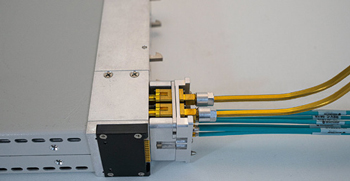
Figure 4 Modular blind-mate interface and fixture.
Fixturing is a major design consideration for most ATE systems and is much more critical at mmWave frequencies. In many cases, the fixture and interface cards that bridge the test equipment to the device must be custom designed for each device. This limits reusability and creates reliability and test issues by requiring a new interface card design for every DUT. Modular device interface cards and standardized modular fixturing designed with mmWave performance considerations provide better reusability of test system hardware as well as greater reliability and repeatability for high sensitivity measurements (see Figure 4). Moreover, calibration is easier, as a modular device interface can be included in calibration procedures without additional custom calibration. Hence, additional vector error calibration can be performed for both the fixture layer and device interface board layer enabling system-wide vector error calibration down to the device plane.
Other important considerations at mmWave frequencies are control capability, software support and test system optimization features. With rack and stack systems made from bench-top instruments, there may be very limited flexibility and programmability available to the user and interfacing with the ATE manufacturer may be necessary for even relatively minor changes. In other cases, completely generic hardware and software configurations leave the user with the burden of programming an ATE system test routine from scratch. A more modern and user-friendly approach is to provide an extensively featured graphical user interface that can allow the user flexible control while minimizing design complexity and the potential for user error. It is also beneficial for these systems to allow for custom programming to enable additional features and customization to meet the latest standards and conformance testing.
CONCLUSION
mmWave testing is moving from the laboratory to mainstream production. The test industry is now facing challenges posed by both the production environment and highly sensitive and stringent mmWave testing requirements. Modular ATE is likely the only test system solution that can economically deliver production-grade mmWave and mixed-domain testing. 5G, as it goes up in frequency, is one of the first big market sectors entering this space. It forces the ATE industry to face the test challenges in making 5G a reality; much of the ATE industry will be working in the greater than 26 GHz frequency space for the first time.
References
- M. Roos and R. Hayward, “mmWave RFIC Probing Systems for Engineering and Production Test,” IEEE Semiconductor Wafer Test Workshop, June 2009. Web. https://www.swtest.org/swtw_library/2009proc/PDF/S06_02_Roos_SWTW2009.pdf.
- J. Sherry, “Testing of High Frequency 5G Applications and Why Simulation is Critical to Success,” TestConX, March 2019. Web. https://bitsworkshop.org/premium/wp-content/uploads/2019/TestConX20191ap2_3478.pdf.
- J. Mroczkowski, “WLCSP xWave for High Frequency Wafer Probe Applications,” IEEE Semiconductor Wafer Test Workshop, June 2018. Web. www.swtest.org/swtw_library/2018proc/PDF/S04_02_Mroczkowski_SWTW2018.pdf
- J. Mroczkowski and N. Falco, “Solution for mmWave Wafer Probe Applications and Field Results,” TestConX, March 2019. Web. https://bitsworkshop.org/premium/wp-content/uploads/2019/TestConX20191ap1_2290.pdf.