
The automated test and measurement (ATE) landscape is rapidly changing, progressing beyond the capabilities of traditional bench-top and most legacy ATE systems. Varying and diverse performance requirements, testing speeds and frequencies used by modern cellular architectures (5G), Internet-of-Things (IoT) devices, and the latest feature dense systems-on-chip/systems-in-package (SoC/SiP) necessitate a different approach. This leverages a modular configuration focused on precise calibration, low loss device connections and high measurement accuracy with a small footprint and low capital expense. Modular architectures can provide future proof features and enable ATE systems to be faster and more accurate with less development. Not all modular ATE systems are created equal, however. At mmWave frequencies, test system configuration requires insight into the differentiating features between ATE systems as well as the bench-top units they typically replace.
Automated testing of mmWave devices has been subject to increasingly complex standards, methods and requirements over the past few years. This trend is likely to progress as fifth generation cellular mobility (5G), IoT, and system-on-chip (SoC) technologies continue to advance, leaving research and development and moving past engineering volumes to production.1 Current mmWave automated testing relies on dedicated test (bench-top) instruments or custom designed/developed ATE purpose-driven for a specific type of device, standard or set of specifications.
This is an era of rapid technology advancement, shifting standards, and the use of the upper-microwave and mmWave spectrum for mainstream applications (see Figure 1). It is unlikely that general purpose bench-top instruments or custom/application-specific ATE systems will be able to cope with the onslaught of new requirements. Hence, an engineering team selecting production test equipment must be mindful of current and future requirements. Organizations cannot risk purchasing capital equipment that may become rapidly obsolete or provide diminishing value due to complex setup and optimization requirements. There is a need for modular test systems that reach well into the mmWave frequency range, support multi-domain synchronized testing, have software-based configurability and can accommodate the shifting standards of modern cellular, Wi-Fi, IoT and other emerging technologies.
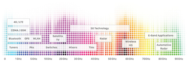
Figure 1 Spectral mapping of applications.
TRENDS & CHALLENGES
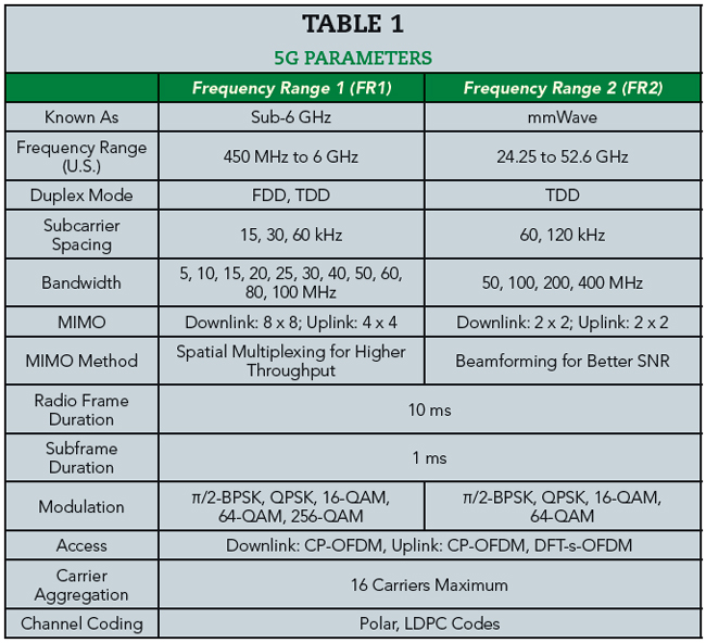
The emerging device trends responsible for the growth of mmWave production testing are: massive numbers of devices that operate at much higher frequencies (to nearly 100 GHz) with bandwidths reaching several hundred megahertz to a gigahertz, more complex and configurable RF devices with multiple RFICs, and testing scenarios that require simultaneous and synchronized mixed-domain (power, RF, analog and digital) measurements and signal generation. Initial 5G user equipment (UE) and customer premise equipment alone are capable of operating in all 4G bands, new 5G sub-6 GHz bands (FR1) and new 5G mmWave bands (FR2), which in the U.S. can include frequencies beyond 50 GHz (see Table 1). These are generally composed of highly integrated and tightly assembled digital, RF, analog and power devices, for which design and operation are dictated by standards that are prone to change over the next several years.
5G, as well as mmWave Wi-Fi (802.11ad), drive test complexity with other features such as multi-input multi-output (MIMO), beamforming and carrier aggregation (CA) that result in antenna systems capable of generating nearly infinite numbers of test cases and combinations of frequency bands (600+ carrier-aggregated combinations with 3GPP release 15).2 This poses challenges for R&D characterization, quality and verification testing where there is little room for lengthy and complex measurements in an industry that is continuously driving down the bottom line in the face of rising competition. To prevent negative reception of early 5G products and services, the telecom industry and UE device manufacturers must also be aware of the market’s low threshold for device failures, which underscores the need for rigorous testing and characterization.
Wi-Fi (802.11ad, 802.11ax) and 5G CHALLENGES
The latest high throughput and high complexity SoCs/SiPs employ various styles of built-in-self test and test sequence automation to aid with chip-level testing and manufacturer verification. In some cases, these tests are performed rapidly, with some occurring within hundreds of microseconds. For RF test equipment to keep pace, equipment settling times must match or exceed these windows. Multi-domain testing, as well as direct circuit testing and over-the-air (OTA) testing must be done simultaneously with synchronized test equipment. For example, cellular handsets that have Wi-Fi, Bluetooth, 3G/4G/5G FR1 cellular and near field communications modules may require both OTA and direct circuit probing to test intersystem interference, which is compounded by new CA technologies where several cellular bands may be simultaneously used.
Wide dynamic range and frequency range OTA testing is also essential for characterizing and verifying MIMO/beamforming antenna systems. In the cases where each antenna element must be inspected, high dynamic range is necessary to determine the performance of each element, especially when some elements may exhibit much higher signal power levels than their defective neighbors. Discovering defective elements may be impossible without direct testing of each antenna element. For upcoming 64×64 MIMO 5G base station antenna systems, this testing may be impractical due to the time required, the cost and the setup complexity. To test large numbers of systems, test repeatability and optimization are crucial for 5G UE and base stations to be both economical and perform reliably in the field.
NEW ERA FOR PRODUCTION TESTING
Until recently, the mmWave arena has been dominated by the government and military for radar and satellite communications with a small amount of commercial backhaul products. MmWave products have historically been high cost and low volume where hand testing with traditional bench equipment was acceptable (see Figure 2a). The high volume and low cost consumer market traditionally remained below 6 GHz. ATE systems evolved in the sub 6 GHz range to meet the fast, low cost test needs of consumer products. Now volume production is reaching into mmWaves and extending the need for fast low cost testing that maintains accuracy in frequencies where high accuracy has previously been impractical.
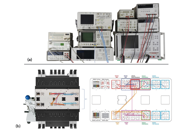
Figure 2 Legacy bench-top (a) and modular production (b) test systems.
Production ATE systems also generally offer much more granular control over the operation of the test equipment RF components, which only some bench-top units offer; and, the ones that do generally require custom setups. Given the stringent requirements of mmWave testing, it is conceivable to use approaches that have largely been ignored or undiscovered by mainstream test and measurement device manufacturers who have mostly focused on either large format all-in-one bench-top instruments or highly integrated and limited field portable test units.
As a result, there is a growing number of test equipment manufacturers building modular test equipment platforms designed with components that can be configured in a variety of ways to meet unique test needs (see Figure 2b). These are focused on sub-6 GHz technology to serve R&D, specialized and production test scenarios with low cost and configurability requirements. The general purpose modular test units often require customized setups and programming to build viable platforms and generally do not offer the same level of performance and reliability as traditional bench-top units.
mmWAVE MODULAR ATE FEATURES
There are many frequency dependent phenomena associated with RF testing, some of which become major test system design challenges at mmWave frequencies. Test systems that are not designed with these in mind may be much less accurate and may even yield misleading or inconsistent results at frequencies above several gigahertz. Some of these phenomena drive mechanical/electrical (physical) test system design, while others influence test system architectures.
Interconnects, Probes, Match and Loss
At mmWave frequencies the conductivity of metals decreases as a function of frequency and the dielectric loss of insulators increases. Moreover, the much smaller wavelengths of mmWave signals interact with geometric features that exhibit minimal impact at lower frequencies. For example, a quarter-wavelength in air at 1 GHz is 75 mm, while at 80 GHz it is less than 1 mm; hence, interconnects that work adequately at lower frequencies do not scale to mmWave.