

There are three types of beamforming architecture that have direct impact on the energy efficiency of the base station and the UE (see Figure 7):
- Analog Beamforming (ABF): The traditional way to form beams is to use attenuators and phase shifters as part of the analog RF circuit where a single data stream is divided into separate paths. The advantage of this method is that there is only one RF chain (LNA, filters, switch/circulator) required. The disadvantage is the loss from the cascaded phase shifters at high power.
- Digital Beamforming (DBF): DBF assumes there is a separate RF chain for each antenna element. The beam is then “formed” by matrix-type operations in the baseband where artificial amplitude and phase weighting is performed. For frequencies lower than 7 GHz in 5G FR1, this is the preferred method since the RF chain components are comparatively inexpensive and can combine MIMO and beamforming into a single array. For frequencies of 28 GHz and above, the PAs and ADCs are very lossy for standard CMOS components. If exotic materials, such as GaAs and GaN are used, the losses decrease at the expense of higher cost.
- Hybrid Beamforming (HBF): HBF combines DBF with ABF in order to allow the flexibility of multiple radio transceivers plus beamforming while reducing the cost and losses of the beamforming unit (BFU). Each data stream has its own separate analog BFU with a set of M antennas. If there are N data streams, then there are NxM antennas. The analog BFU loss due to phase shifters can be mitigated by replacing the adaptive phase shifters with a selective beamformer such as a Butler matrix. One proposed architecture uses the digital BFU to steer the direction of the main beam while the analog BFU steers the beam within the digital envelop.
OPTIMAL NETWORKS: SPECTRAL AND ENERGY EFFICIENCY
The combination of C-RAN, MIMO, new spectrum and beamforming allows 5G to both increase capacity while decreasing costs compared to traditional and current cellular networks. The Shannon-Hartley theorem can be reformulated to take into account the energy efficiency of the channel.2 Using the constraints in the performance of the base stations and the network, the joint optimal spectral-energy efficiency of 2G and 4G networks can be calculated at 4 bps/Hz for GSM and 8 bps/Hz for LTE. Note, in real networks, these values are often lower at 4 bps/Hz for LTE.
The combination of MIMO and digital beamforming in 5G FR1 can lead to an increase of capacity of over 3x compared to an LTE network while decreasing costs by a factor of 10 (assuming that there are eight transceivers per user with beamforming). While 5G FR1 has limited frequency spectrum available, 5G FR2 uses large amounts of spectrum above 24 GHz. The spectral efficiency of 5G FR2 (assuming HBF with eight transceivers per antenna array) is comparable to LTE at 10 bps/Hz, but with higher energy efficiency compared to LTE4 (see Figure 8).
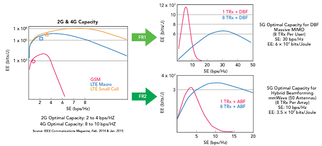
Figure 8 Optimized networks: spectral and energy efficiency.
In conclusion, the combination of spectral and energy efficiency allows operators to deploy new networks that can simultaneously boost capacity while lowering OPEX. Networks of the future will combine the different solutions of FR1 and FR2 into single networks, allowing the FR1 to deliver high dates in a wide area network with in-building penetration while FR2 serves as data off-loading, hotspots and extreme network densification. This network deployment will not only affect consumers and equipment vendors, but also has a fundamental impact on the entire test & measurement industry.
IMPACT ON TEST & MEASUREMENT INDUSTRY
The new base stations required for 5G result in a new measurement paradigm with the use of over-the-air (OTA) testing for both antenna and transceiver performance characterization.
5G BASE STATION ARCHITECTURE
The combination of beamforming and MIMO into a single array leads to a massive MIMO base station as multiple sets of antennas are required for both beamforming (same data vector for each antenna) and MIMO (different data vectors for each set of beamforming antennas). Designing these base stations so that both spectral and energy efficiency can be increased is complex and requires very tight integration of all the components (see Figure 9):
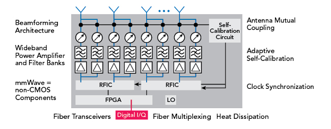
Figure 9 Massive MIMO architecture.
- Beamforming Architecture: This depends on the availability of components both in terms of losses (energy efficiency) and cost.
- Wideband Power Amplifier and Filter Banks: The increase of the number of frequency bands, carrier aggregation across wide frequency bands will require large numbers of both filters and power amplifiers. The power amplifiers will require pre-distortion or exotic materials to operate at higher efficiencies.
- Antenna Mutual Coupling: Simply packing more antennas into a space will decrease the capacity and increase the losses in the base station.
- Clock Synchronization: For a large massive MIMO array, the clocks will require synchronization over separate PCB boards. Clock drift will lead to uncertain phase changes (due to frequency drift) between the antennas and decrease the effect of beamforming.
- Adaptive Self-Calibration: Due to the large numbers of components, chipsets, clocks and amplifiers, together with the dependency of phase on temperature conditions inside the base station, the output phase at each antenna can vary significantly from the desired phase. Therefore, an adaptive self-calibrating circuit is required where the phase and amplitude offset of each signal is measured and is then pre-distorted so that optimal beamforming can be achieved.
- Fiber Transceivers: The output of the massive MIMO base station is typically baseband that is then transmitted through fiber to either a local baseband unit or into the C-RAN. Consequently, a real-time FPGA is required to translate the output baseband data from the RFIC to the baseband protocol for fiber.
- Heat Dissipation: The combination of up to hundreds of antennas, thousands of components and dozens of RFICs/FPGAs within a confined space leads to significant heat and thermal issues. As these units are deployed without externally provided air cooling in areas of large temperature variation, large heatsinks are required, significantly increasing the weight of the massive MIMO unit.
TEST & MEASUREMENT OF 5G BASE STATIONS AND DEVICES
Traditionally, the performance of a base station was measured by separating the antenna portion from the radio/RF portion. The modulated performance of the RF transceivers could be measured directly with cables between the RF test ports and the measurement instruments (i.e., vector signal analyzer and signal generators). The antenna performance was typically measured OTA using CW waveforms with a vector network analyzer.
Figure 10 New measurement paradigm for 5G.
Due to the highly integrated architecture of the massive MIMO base station, there is no longer direct access to the individual RF paths. This implies a fundamental change of measurement philosophy by moving away from highly predictable cable measurements of the RF transceivers to a more chaotic environment consisting of OTA measurements (see Figure 10).
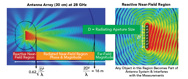
Figure 11 Antenna electromagnetic fields.
Figure 12 Plane wave converter and CATR.
OTA measurements are significantly more complex than cable measurements due to the different physical properties of the radiated fields (see Figure 11) in the near-field and far-field regions of the device under test (DUT). Due to both the time and spatial-varying properties of the modulated signals, measurements must be performed in the far-field of the DUT (planar waves), resulting in either very large anechoic antenna chambers or indirect far field chambers such as the plane wave converter (PWC) or compact antenna test range (CATR). A CATR uses a reflector to convert a spherical wave to a planar wave distribution in the near field of the reflector and the PWC uses an array to generate a planar wave distribution in the near field of the array (see Figure 12).
Due to the elimination of RF test ports and the use of frequencies in the millimeter region, OTA will become an essential tool for characterizing the performance of not just the antenna arrays of an active antenna system of a massive MIMO array, but the internal transceivers as well. For this reason there will be a high demand for OTA chambers and measurement equipment to not only measure the strict radiative properties of antennas, but substituting traditional conducted transceiver measurements as well. Rohde & Schwarz, with its wide range of anechoic chambers and measurement equipment expertise, is well situated to deliver solutions even for future customer requirements.5
References
- CMRI, “C-RAN: The Road Towards Green RAN,” December 2013.
- I. Chih Lin, C. Rowell et al., “Towards Green and Soft: A 5G Perspective,” IEEE Communications Magazine, February 2014.
- F. Rusek et al., “Scaling Up MIMO: Opportunities and Challenges with Very Large Arrays,” IEEE Signal Processing Magazine, January 2013.
- H. Shuangfeng et al., “Large Scale Antenna Systems with Hybrid Analog and Digital Beamforming for Millimeter Wave 5G,” IEEE Communications Magazine, January 2015.
- “Antenna Array Testing - Conducted and Over the Air: The Way to 5G,” Rohde & Schwarz White Paper, 2016.