
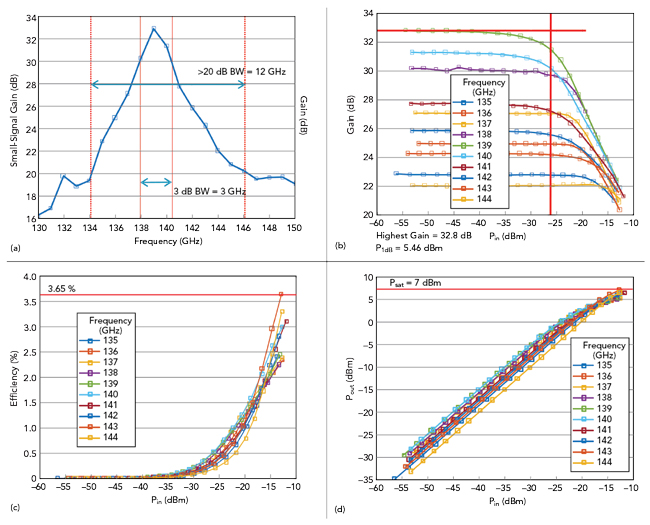
Figure 4 Measured performance of a two-stage, 130 nm SiGe BiCMOS amplifier, showing the small-signal gain vs. frequency (a), gain vs. Pin (b), efficiency vs. Pin (c) and Pout vs. Pin (d).
SUB-THz ACTIVE LOAD-PULL
As shown in the previous section, using a four-step calibration and the aid of external computation enables large-signal measurements at mmWave frequencies by employing off-the-shelf equipment designed for small-signal measurements, i.e., the same equipment commonly used for simple, non-power controlled, S-parameter measurements. The large-signal capabilities of the setup, however, are limited, and only matched measurements can be performed, since the load or source impedance presented to the DUT cannot be changed with respect to the system intrinsic impedance.
To perform more advanced measurements (i.e., active load-pull), the hardware setup needs improvement. The realization of an active load-pull setup requires an active tuner, which changes the impedance condition by properly injecting a defined signal, controllable both in phase and amplitude, into the DUT terminal. Considering the system previously described, while it is possible to modulate the power injected into the DUT, no phase control is available.
To incorporate phase control, a programmable phase shifter must be inserted into the signal injection path. The intuitive solution is to place the phase shifter just before the reflectometer, enabling phase modulation directly on the frequency-multiplied signal (see Figure 5a). This implies modification of the mmWave extender by employing a mmWave phase modulator. While suitable from a measurement perspective, the high cost of such a component with the complexity of a hardware modification inside a mmWave extender makes this solution unrealistic. If, however, the phase shifter is placed before the mmWave extender (see Figure 5b), phase modulation is performed on the RF signal before frequency multiplication, thus at a lower frequency with respect to the measurement. This allows more flexibility and a lower cost, since lower frequency components are used for the phase shifter and the waveguide extender need not be modified.
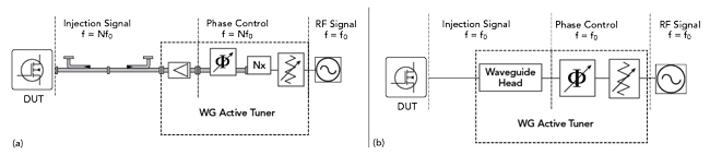
Figure 5 Two active tuner implementations: modulating the injected signal after (a) and before frequency multiplication (b).
FREQUENCY SCALABLE ACTIVE TUNER
Once the topology of Figure 5b is chosen, the actual implementation must be defined. The choice of the waveguide head is defined by the specific frequency range, which, in principle, is arbitrary, as it does not affect the lower frequency hardware. For the amplitude and phase modulation, appropriate components must be chosen. In the case of MMW-STUDIO, amplitude (power) modulation of the injection signal is obtained directly from the RF source of the VNA, while power control is achieved by means of calibration.
For an open loop active load-pull architecture, one of the main requirements is phase coherence between the injected waves at the input and the output of the DUT: the two injected signals must share the same time base. The easiest and most reliable approach is for the two injected waves at the test ports to share the same RF source.7 If that is the case, and it is desired to use just one RF source of the VNA to control both injections, it is not possible to independently control the power at each port with the same source. If independent power modulation at the two ports is required, another solution must be used. The use of I/Q modulators, as in mixed signal active load-pull8 at mmWave frequencies,6 could allow both power and phase modulation for each port, independently. The main difference with mixed signal active load-pull is that signal modulation is performed at a different frequency than the measurement frequency.
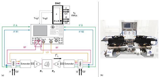
Figure 6 The scalable active load-pull test bench for measurements at sub-THz frequencies (a) and view of the complete on-wafer active load-pull system (b).
Using these considerations, the classical schematic of Figure 3a is modified in Figure 6a to achieve active load-pull capabilities. Figure 6a is a simplified block diagram of the implementation realized by Vertigo Technologies, where the I/Q modulators are embedded in general vector modulation units (VMU). The VMUs are both driven by port 1 of the VNA through a power splitter, to ensure total phase coherence, at a fixed power. The I/Q modulators are used as phase/amplitude modulators with DC signals (I and Q) generated through a high bit count (24-bit) digital-to-analog converter that is synchronized with the VNA through a handshaking loop to ensure high speed. The frequency at which the VMUs operate is the same as the RF input frequency of the extender modules, typically in the range between 5 and 20 GHz for most commercially available extenders for output frequencies to 1.1 THz. The signal modulated by the VMU is presented to the extenders and is up-converted to the desired frequency. The up-converted signal becomes the injection signal for the active tuner; using an iterative procedure, it is possible to perform active load-pull measurements.
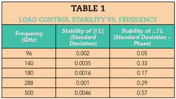
Figure 6b shows a practical implementation of a complete on-wafer active load-pull system working in the WR6.5 waveguide band (110 to 170 GHz). The VMUs for both the input and the output are conveniently assembled in a single rack-mount case for ease of mounting and signal distribution. The system of Figure 6b, together with the MMW-STUDIO LP software, can perform active load-pull measurements at any desired load impedance (depending on the DUT and the extender specifications), ideally at every frequency covered by mmWave extenders. This setup has been tested up to 500 GHz with stability better than 0.01 in magnitude and 0.6 degrees in phase. Table 1 shows a summary of load control stability at different measured frequencies.
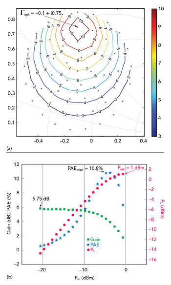
Figure 7 Active load-pull measurements of a two-fingered, 130 nm SiGe BiCMOS HBT at 125 GHz, showing the PAE contours (a) and the gain, PAE and power delivered to the load at the optimum PAE load (b).
Figure 7 shows the large-signal characterization of a commercial, double-finger 130 nm SiGe BiCMOS HBT. The test was performed at 125 GHz with more than 54 different loading conditions and an input power sweep from −21 to −1 dBm. ZC140 extender modules from Rohde & Schwarz were used, featuring a nominal available power of 8 dBm. Figure 7a shows the power-added efficiency (PAE) contours, identifying the optimum loading condition for peak PAE: Γopt = −0.1 + i0.75. Figure 7b shows the measured gain, PAE and power delivered to the load (PL) versus the input power, Pin, at Γopt. To the authors’ knowledge, the results of Figure 7 represent the first published active load-pull measurements of an active device at frequencies higher than 110 GHz.
CONCLUSION
With the aid of software, dedicated calibration and small hardware modifications, it is possible to expand the capabilities of conventional waveguide extender-based VNA setups to perform accurate power control, power sweeps and active load-pull measurements in the sub-THz frequency range. The described approach is scalable to every frequency band covered by mmWave waveguide extenders and has been tested to 500 GHz. Measurements of commercial BiCMOS devices at 125 GHz show the capability of this approach to fully characterize realistic devices using off-the-shelf equipment.
References
- “LXI™ Millimeter-Wave Automated Tuners Data Sheet 4T-050G05,” Maury Microwave, www.maurymw.com/pdf/datasheets/4T-050G05.pdf.
- “MT1000 and MT2000–Mixed-Signal Active Load Pull System (1 MHz to 40 GHz) and MT2001 System Software Data Sheet 4T-097,” Maury Microwave, www.maurymw.com/pdf/datasheets/4T-097.pdf.
- L. Galatro, M. Marchetti and M. Spirito, “60 GHz Mixed Signal Active Load-Pull System for Millimeter Wave Devices Characterization,” Proceedings of the 80th ARFTG Microwave Measurement Conference, November 2012.
- V. Teppati, H. Benedickter, D. Marti, M. Garelli, S. Tirelli, R. Lövblom, R. Flückiger, M. Alexandrova, O. Ostinelli and C. R. Bolognesi, “A W-Band On-Wafer Active Load-Pull System Based on Down-Conversion Techniques,” IEEE Transactions on Microwave Theory and Techniques, Vol. 62, No. 1, January 2014, pp. 148–153.
- C. De Martino, Z. Hu, L. Galatro, G. Sarris and M. Spirito, “Power Level Control of mmWave Test Benches for Accurate Small and Large-Signal DUT Measurements,” Proceedings of the 88th ARFTG Microwave Measurement Conference, December 2016.
- L. Galatro, S. Galbano, A. Santaniello and M. Spirito, “Power Control for S-parameters and Large Signal Characterization at (sub)-mmWave Frequencies,” Proceedings of the 85th ARFTG Microwave Measurement Conference, May 2015.
- Y. Takayama, “A New Load-Pull Characterization Method for Microwave Power Transistors,” IEEE MTT-S International Microwave Symposium Digest, June 1976, pp. 218–220.
- M. Marchetti, M. Pelk, K. Buismann, W. Neo, M. Spirito and L. C. N. de Vreede, “Active Harmonic Load-Pull with Realistic Wideband Communication Signals,” IEEE Transactions on Microwave Theory & Techniques, Vol. 54, No. 12, December 2008, pp. 2979–2988.