
Characterizing electronic devices and MMICs at sub-THz frequencies presents several challenges for the instrumentation. While S-parameter measurements can be performed using vector network analyzers (VNA) with mmWave extenders, large-signal measurements require dedicated measurement setups. A novel approach, described here, expands the capabilities of conventional VNA sub-THz S-parameter setups to achieve refined power control, power sweeps and active load-pull.
The increasing performance of semiconductor technologies in terms of ft and fmax is fostering the development of new commercial applications in the mmWave frequency range. Examples can be found in the development of 5G communication with frequencies up to 80 GHz, automotive radar at 77, 94 and 140 GHz, SATCOM, imaging and home entertainment.
Development for commercial applications inevitably includes characterization of single active devices (i.e., transistors) as well as the testing of ICs such as power amplifiers, detectors and radiometers. The first is to extract and verify the device compact model for frequencies as high as ft or fmax. The latter is to verify IC compliance with the requirements of the final application. Regardless of the scope, the availability of accurate and reliable test instrumentation is fundamental for technology development.
Active device small- and large-signal characteristics must be determined. The first step is typically the measurement of the S-parameters, which can be achieved using VNAs. Broadband VNAs with coaxial extenders are commercially available up to 220 GHz, while waveguide-banded solutions are available up to 1.5 THz. Limitations of these setups are primarily related to available power, losses in interconnections with increasing frequency (especially for broadband coaxial setups) and the difficulty of controlling power delivered to the device under test (DUT) when waveguide-banded extender modules are used.
For large-signal measurements, one of the most popular techniques is load-pull. Passive tuners are available commercially for frequencies as high as 110 GHz,1 but performance is generally limited by increased losses at mmWave frequencies, which limits the reflection coefficient that can be presented to the DUT load. Commercial active load-pull systems are currently only available for frequencies lower than 40 GHz.2 Few examples of active load-pull systems exist in the literature at higher frequencies,3-4 and they are all based on dedicated implementations that are generally not scalable.
This article describes a measurement approach employing a conventional mmWave VNA with waveguide-banded extenders that has refined power control and power sweep capabilities at any frequency bandwidth covered by the waveguide extenders. With small modifications, the setup can be enhanced to include active tuning capabilities, becoming the first scalable active load-pull setup for sub-THz frequencies.
POWER CONTROL LIMITATIONS
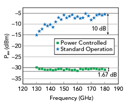
Figure 1 Output power of a commercial WR5 waveguide extender module showing the nominal output power and a constant –30 dBm set with MMW-STUDIO.
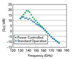
Figure 2 Measured gain vs. frequency of a two-stage, 130 nm SiGe BiCMOS amplifier using waveguide extenders, comparing nominal power from the extender to power control.
For conventional VNA measurements, dynamic range is maximized through power control, which is achieved with the hardware using a feedback architecture called automatic level control (ALC). When mmWave waveguide extenders are used, ALC is implicitly excluded from the measurement loop. Due to the absence of an ALC within the extenders and the nonlinear nature of the internal components, the power available from the source can vary significantly within the waveguide band. An example is shown in Figure 1, where the output power (Pav) of a commercially available WR-05 VNA extender is displayed, with a nominal fixed power at the RF input port of the module. In the figure, the power fluctuation is on the order of 10 dB. Similar values can be expected at all bandwidths, depending on the manufacturer.
This lack of power control to the DUT has different implications on the measurement accuracy of active devices. When performing small-signal measurements, if the power level at the input of the DUT fluctuates and cannot be properly controlled, the risk is to either drive the device into an incorrect operating regime - compromising the small-signal characterization - or to reduce the input power level to ensure proper operation and restrict the dynamic range of the measurement.
An example related to reduced power control capability is illustrated by De Martino et al.5 in the characterization of a 140 GHz power amplifier. When the DUT, a two-stage 130 nm SiGe BiCMOS amplifier, is characterized using waveguide extenders with a nominal output power, the S-parameters are incorrectly represented in the frequency range between 135 and 160 GHz (see Figure 2).
COMPUTER-AIDED POWER CONTROL AND SWEEPS
The absence of ALC when using mmWave waveguide extenders can be circumvented using a dedicated software control loop. Consider the simplified schematic of a conventional VNA setup for mmWave measurements employing extenders, shown in Figure 3a, with the addition of an external computer and a power sensor for power calibration. As described by Galatro et al.,6 power control can be achieved with the following steps (see Figure 3b):
1. S-parameter calibration at the waveguide reference planes.
2. Power calibration by connecting a power sensor to waveguide port 1 and measuring the absolute power during a frequency sweep.
3. Power leveling: nonlinear power responses of the extender modules are characterized over large sweeps of input power and frequency while measuring the power delivered at the waveguide test port directly using the VNA receivers. This uses the power calibration performed in Step 2.
4. On-wafer calibration shifts all the calibration reference planes (S-parameter, power and leveling) to the desired on-wafer reference plane.
After this four-step procedure, it is possible to accurately control and measure the power provided to the DUT using the high dynamic range and speed of commercial VNAs, as the use of slower and low dynamic range power meters is limited to the power calibration in Step 2.
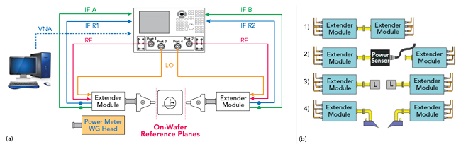
Figure 3 Conventional mmWave measurement using waveguide extenders with a 4-port, two-source VNA (a) and the four-step calibration procedure (b).
IMPACT OF POWER CONTROL
The capability of controlling power during S-parameter measurements alleviates measurement inaccuracies related to improper device driving. For example, the device described by De Martino was tested using the power control procedure described above and embedded in MMW-STUDIO, a software platform developed by Vertigo Technologies and TU Delft for accurate sub-THz measurements. In this case, the power is maintained at −30 dBm over the entire frequency range (see Figure 1) to ensure small-signal operation. This ensures correct measurement of the S-parameters as shown in Figure 2, where S21 is accurately characterized over the entire bandwidth.
The four-step procedure described enables doing more than just controlling power during S-parameter measurements. The capability of controlling and measuring power can also be used to perform power sweeps to derive large-signal characteristics such as gain compression. Figure 4 shows measurement results for power sweeps at different frequencies of the PA described above. Note that the measurement of approximately 250 data points took only about 4.5 minutes, compared to 2 hours to properly perform all the measurements using a power meter setup.