
Simulation
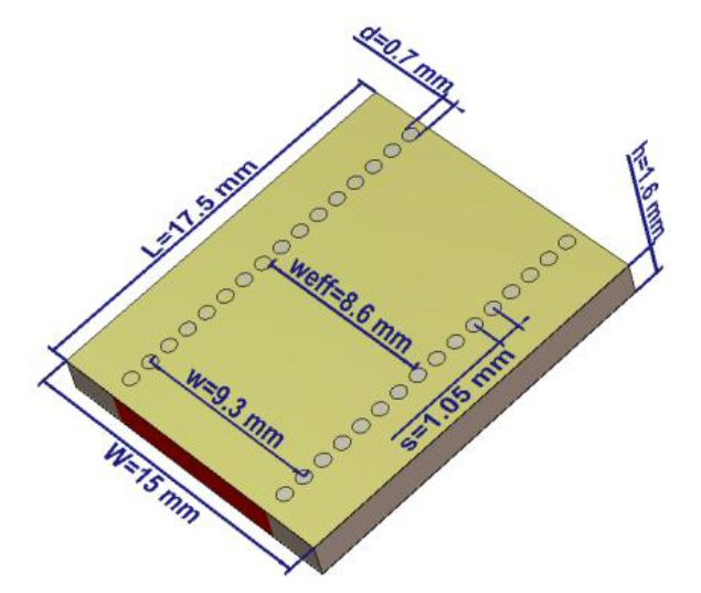
A SIW is designed on a double-sided copper clad Rogers 6002s substrate with dielectric loss equal to 0.0012 and a permittivity of 2.94. The basic dimensions are calculated using Equations 1 through 10. The structure in Figure 2 is simulated using CST-Microwave studio. Table 1 lists the dimensions.
| Parameter | Symbol | Value (mm) |
|---|---|---|
| Substrate width | W | 15 |
| Substrate length | L | 17.5 |
| Substrate height | h | 1.6 |
| Via diameter | d | 0.7 |
| Spacing(pitch) | s | 1.05 |
| SIW width | w | 9.3 |
| Effective width | weff | 8.6 |
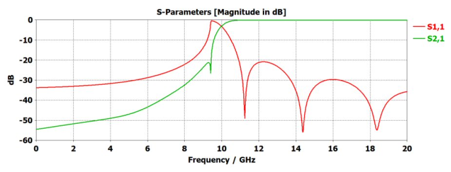
S-parameters of the SIW (see Figure 3) show a cutoff frequency of 11 GHz with a minimum pass band insertion loss and an in-band return loss greater than 10 dB.
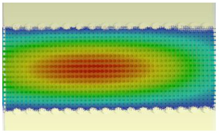
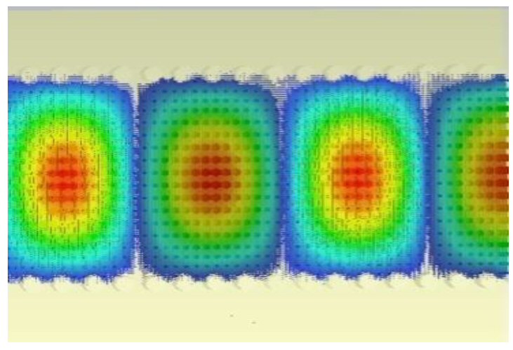
Figures 4 and 5 represent the electric field distribution of the structure at 11 and 20 GHz, respectively. It is evident that the field is bounded within the SIW vias.
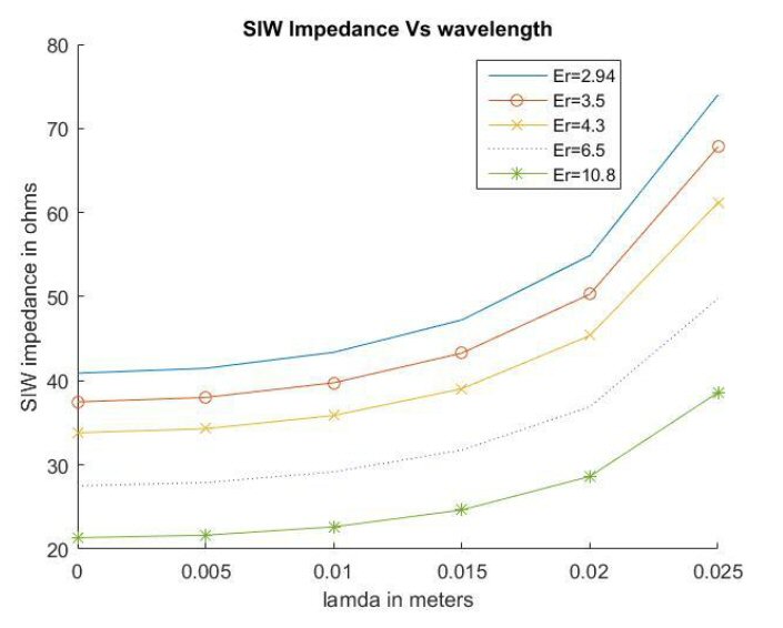
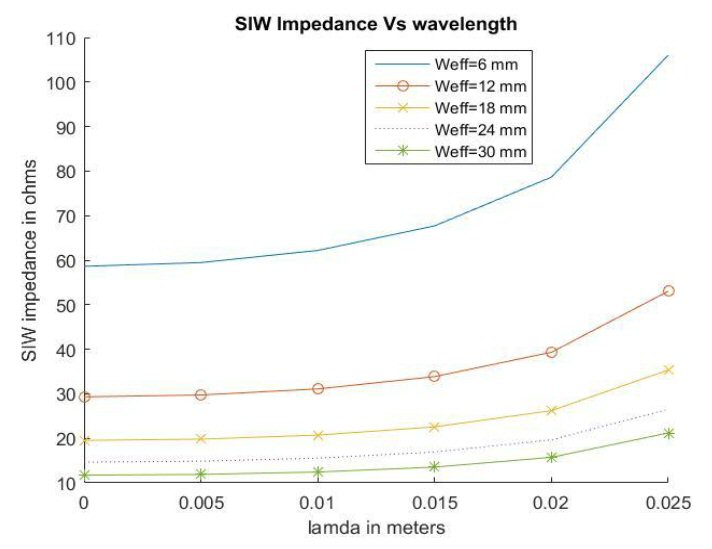
The SIW impedance and phase constant are calculated using Equations 11 through 13. The variation of SIW impedance for different dielectric constants (with constant effective width 8.6 mm) and different effective widths (with constant dielectric constant of 2.94) is shown in Figures 6 and 7, respectively. It is inferred from Figure 6 that impedance is inversely proportional to the dielectric constant for constant weff. Also, Figure 7 shows that impedance is inversely proportional to effective width for a constant εr.
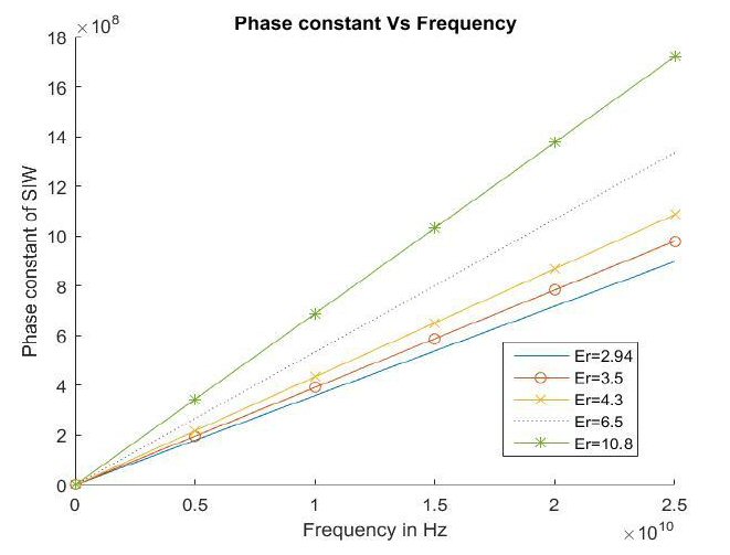
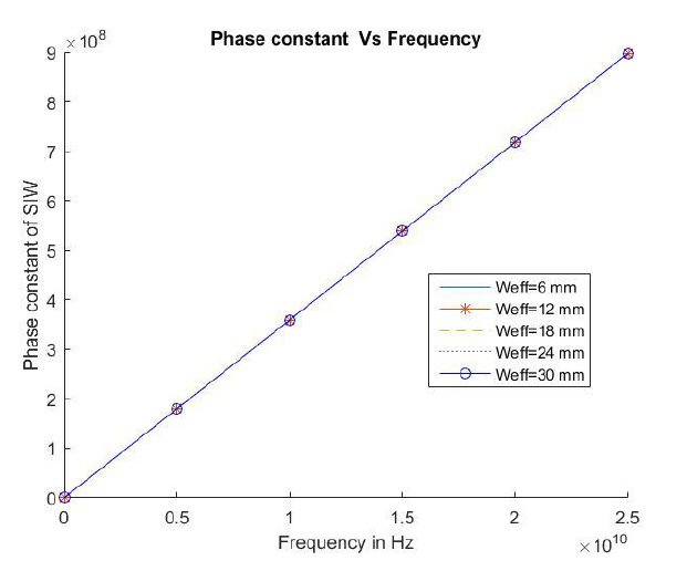
Analysis of the SIW phase constant for different dielectric constants (with constant effective width 8.6 mm) and different effective widths (with a constant dielectric constant of 2.94) is shown in Figures 8 and 9, respectively. From Figure 8, the phase constant increases with increasing dielectric constant. Figure 9 shows that the phase constant is independent of effective width.
Conclusion
A theory for the design of SIW is developed. A SIW with a cutoff frequency of 11 GHz is designed using CST-MWS. S-parameters show a sharp cutoff at 11 GHz. The electric field is confined within the SIW vias and there is no leakage. SIW characteristics such as impedance and phase constant analyzed using MATLAB show that impedance is inversely proportional to dielectric constant and effective width of equivalent waveguide, whereas the phase constant is directly proportional to the dielectric constant and independent of effective width of equivalent waveguide. SIW characteristics make it a suitable candidate for miniaturized, low loss, high power handling planar components.
References
- H. Uchimura, T. Takenoshita and M. Fujii, “Development of a ‘Laminated Waveguide’," IEEE Transactions on Microwave Theory and Techniques, Vol. 46, No.12, December 1998, pp. 2438-2443.
- K. Wu, “Integration and Interconnect Techniques of Planar and Nonplanar Structures for Microwave and Millimeter-Wave Circuits - Current Status and Future Trend,” Proceedings of the Asia–Pacific Microwave-Conference, December 2001, pp. 411-416.
- K.Wu, D.Deslandes and Y.Cassivi, “The Substrate Integrated Circuits – A New Concept for High Frequency Electronics and Optoelectronics,” International Conference on Telecommunications in Modern Satellite, Cable and Broadcasting Service, October 2003.
- Y. J. Cheng, K. Wu and W. Hong, “Power Handling Capability of Substrate Integrated Waveguide Interconnects and Related Transmission Line Systems,” IEEE Transactions on Advanced Packaging, Vol. 31, No. 4, November 2008, pp. 900-909.
- R. R. Mansour, “High-Q Tunable Dielectric Resonator Filters,” IEEE Microwave Magazine, Vol. 10, No. 6, October 2009, pp. 84-98.
- X. P. Chen and K. Wu, “Substrate Integrated Waveguide Filter: Basic Design Rules and Fundamental Structure Features,” I__EEE Microwave Magazine, Vol. 15, No. 5, July 2014, pp. 108-116.
- Y. Cassivi, L. Perregrini, P. Arcioni, M. Bressan and K. Wu, “Dispersion Characteristics of Substrate Integrated Rectangular Waveguide,” IEEE Microwave and Wireless Components Letters, Vol. 12, No. 1, September 2002, pp. 333-335.
- R. E. Collin, “Field Theory of Guided Waves,” IEEE Press, 1991.
- F. Xu and K. Wu, “Guided-Wave and Leakage Characteristics of Substrate Integrated Waveguide,” IEEE Transactions on Microwave Theory and Techniques, Vol. 53, No. 1, January 2005, pp. 66-73.
- L. Yan, W. Hong, K. Wu and T. J. Cui, “Investigations on the Propagation Characteristics of the Substrate Integrated Wave-Guide Based on the Method of Lines,” IEE _Proceedings—_Microwaves, Antennas and Propagation, Vol. 152, No. 1, February 2005, pp. 35-42.
- L. Yan, W. Hong, G. Hua, J.Chen, K. Wu and T.J.Cui, “Simulation and Experiment on SIW Slot Array Antennas,” IEEE Microwave and Wireless Components Letters, Vol. 14, No. 9, September 2004, pp. 446-448.
- D. Deslandes and K. Wu, “Accurate Modeling, Wave Mechanisms, and Design Considerations of a Substrate Integrated Waveguide,” IEEE Transactions on Microwave Theory and Techniques, Vol. 54, No. 6, June 2006, pp. 2516-2526.