
A set of compact ultra-wideband (UWB) radar transmit/receive modules has been developed using rapid prototyping. The modules are based on tailored microwave filters, off-the-shelf building blocks from a commercial supplier and custom DC biasing circuits. As an intermediate step toward full system miniaturization, the integration of microwave components using this technique enables evaluation of different configurations to improve radar performance with a reduced form factor. The modular transmitter and receiver provide a loop sensitivity of 160 dB with 1 W transmit power and low range sidelobes. These modules are intended for airborne snow probing applications requiring multi-GHz bandwidths to achieve cm-scale vertical resolution. Laboratory test results indicate an overall performance improvement compared to larger connectorized assemblies, and radar images demonstrate the utility of the modules for measuring snow layers on terrestrial and marine ice from long-range aircraft. This work was funded by the Department of Energy’s Kansas City National Security Campus, operated by Honeywell Federal Manufacturing & Technologies LLC, under contract number DE-NA0002839 and the National Aeronautics and Space Administration (grant NNX10AT68G).
UWB microwave radars are widely used for a variety of applications ranging from medical imaging and detection of concealed objects to airborne geophysical surveys and mapping of infrastructure.1-4 Because of their broad operating bandwidths, such instruments are able to resolve closely spaced targets and media interfaces, making them ideal for measurements of snow thickness and mapping of seasonal snowpack changes (see Figure 1).5 The University of Kansas’ UWB snow radar is a 2 to 18 GHz, frequency modulated continuous wave (FMCW) system, originally developed for gauging snow depth on sea ice and mapping nival accumulation with cm resolution.6 Previous versions of this instrument employed either a connectorized or a hybrid connectorized/printed circuit board (PCB) assembly in the RF section and were used to demonstrate UWB performance onboard large fixed-wing aircraft for wide coverage retrieval of snow thickness information.6-7

Figure 1 UWB radar can measure snow thickness and map seasonal changes in the snowpack.
Future applications, such as operation on unmanned aerial vehicles, require reduction of the radar’s SWaP. As an intermediate step toward complete system miniaturization, modular components from a commercial supplier, X-Microwave,8 were used to evaluate different receiver and transmitter configurations. The technique uses passive and active components mounted on discrete PCB carriers arranged in a grid pattern and connected by flexible ground-signal-ground (GSG) jumpers. Such an approach is convenient for optimizing the radar’s RF performance - linearity, receiver sensitivity, transmit power and overall performance - before committing to a final design. It also enables suitable chipsets, available in both packaged and discrete die formats, to be identified for future miniaturization.
A 2 to 18 GHz radar reference system using commercial connectorized parts was first built to establish a performance baseline. This radar testbed was characterized in the laboratory and used to collect extensive snow cover data flying on NASA aircraft over the Arctic and Antarctic, supporting Operation IceBridge in 2017.9 Transmitter and receiver modules were subsequently developed using the X-Microwave framework and integrated in an improved radar demonstrator.
This article describes the modular receiver, transmitter and upgraded 2 to 18 GHz radar system. Careful selection and close integration of these components improved radar performance and demonstrated the utility of the new modules for airborne radar systems measuring the thickness of snow layers.
SYSTEM OVERVIEW
Figure 2 shows a simplified block diagram of the radar system. The waveform generator produces a linear frequency modulated signal (chirp) in the 2 to 18 GHz spectral range. The chirp signal is filtered and amplified by the transmitter before feeding the transmit antenna. The scattered signal from the observed scene is captured by a second antenna and conditioned by the filter and low noise amplifier in the receiver front-end. A replica of the transmit signal is injected into the local oscillator port of the mixer to de-chirp the amplified received signal. The intermediate frequency (IF) at the output of the mixer is highpass filtered to reject spectral content produced by direct coupling between the transmit and receive antennas. The IF signal is amplified and bandpass filtered before being converted by the analog-to-digital converter (ADC) in the data acquisition (DAQ) system, which stores GPS time-stamped range profiles. The radar is carried onboard an airborne platform with the antennas mounted under the fuselage. The fine resolution of the system, due to its UWB operation, is advantageous for the detection of thin snow cover on sea ice and mapping seasonal accumulation of snow on glacial ice or the ground (see Figure 1).6-7
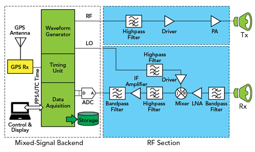
Figure 2 UWB radar block diagram.
Filter Development
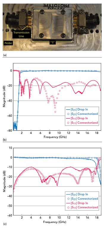
Figure 3 Drop-in highpass filter in a test vehicle (a). Measured drop-in vs. connectorized highpass (b) and lowpass (c) filters.
Microwave filters provide frequency selectivity within the radar, specifically at the receiver input, to eliminate interference from other onboard radar systems operating at VHF (180 to 210 MHz), UHF (600 to 900 MHz) and Ka-Band (32 to 38 GHz). Yan, McDaniel et al.6,10 developed a set of tailored highpass and lowpass filters on suspended substrate stripline, operating from 2 to 18 GHz. The coaxial launch structure of these filters was modified to create a drop-in component compatible with the X-Microwave building block architecture.
The filters installed on a test vehicle (see Figure 3a) enable the transition to planar transmission lines attached to coaxial probes. Figures 3b and 3c show the measured responses for both filters, compensated for probe losses and compared to the discrete implementations. The highpass filter response is comparable to that of its connectorized counterpart, with an overall improvement in return loss over 6.5 to 16 GHz. Return loss for the two implementations is generally comparable up to 8 and beyond 15 GHz, with some differences versus frequency. Roll-off of the drop-in lowpass filter is slightly faster than that of the connectorized implementation. Similar effects in other samples of the same batch, accompanied by good return loss to 18 GHz, indicates differences in filter responses, not an issue with the coaxial launch.
Module Assembly
Multiple chipsets for the receiver and transmitter designs were tested to achieve the best overall performance; in particular, different mixer devices were evaluated to minimize short-range leakage11 or “coherent noise” in the receiver. Coherent noise is an artifact inherent in FMCW radars caused by coupling between the transmitter and receiver through various paths and mechanisms, including the antennas and mixer ports. The main contributors to coherent noise include the chirp’s own phase noise and in-band harmonics, as well as self-mixing products of the main chirp signal with internal reflections. Mixer impedance match and inter-port isolation are critical to minimize coherent noise. Of the wideband mixers evaluated, the best was a connectorized component with field-replaceable connectors, which was used as a drop-in block. Using LO driver amplifiers with low phase noise also improves performance. To achieve at least 1 W output power (versus the 0.1 W in the connectorized reference system), a 4 W capable amplifier under-driven to 1 W was chosen to lower the in-band harmonics and reduce coherent noise.
One of the requirements using the X-Microwave building blocks is precise alignment between the adjacent carriers in a component chain with their corresponding GSG jumpers. Full-wave electromagnetic simulation was used to better understand and predict the effect of misalignment in interconnect performance, including a parametric analysis in which the GSG jumper’s horizontal position was varied from 0 (perfectly aligned) to 6 mils (severely misaligned). Both the transmission and reflection coefficients were satisfactory well beyond 20 GHz when the alignment was within 3 mils from nominal. In practice, alignment of the interconnects is achieved by using registration marks built into the carrier boards and installing them under a high magnification microscope. Blocks are assembled in custom fixtures with the DC power circuitry mounted on the back. Active biasing chips ensure proper power sequencing of the GaN amplifiers. Passive gain equalizers and surface-mount attenuators improve overall the gain and return loss as a function of frequency. Figure 4 shows the assembled transmitter and receiver modules.

Figure 4 Tx (a) and Rx (b) modules.
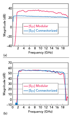
Figure 5 Measured Tx insertion gain (a) and Rx conversion gain (b).