
An antenna for WiMAX at 3.7 GHz and WLAN at 5.8 GHz consists of an asymmetric triangular metamaterial structure fed by coplanar waveguide (CPW). The characteristics of the structure are studied using parametric retrieval and eigenmode analysis. Measured performance is in good agreement with simulation. Owing to its single layer 50 Ω CPW design, this antenna is easily integrated with other RF circuits.
Use of WiMAX and WLAN is now widespread, and antenna technologies are emerging for these applications. WiMAX, also known as IEEE 802.16e, is a broadband wireless access standard generally operating in the frequency range from 2 to 6 GHz, that provides both high speed data services and user mobility. In December 2010, the International Telecommunication Union officially included WiMAX in the 4G standard. Compared with LTE, WiMAX has lower network installation costs and is popular in many regions. Multiband antennas have been explored for WiMAX and WLAN applications1-3 using traditional methods with stacked layers,4 slotted microstrip patches5 or Yagi arrays with different length elements.6 These structures, however, are complicated and therefore difficult to fabricate and, for this reason, are generally unsuitable for most commercial applications. The design of a practical compact multiband antenna remains the subject of ongoing research. Multiband antennas that utilize metamaterials,7 including open complementary split ring resonators used in printed monopole antennas8-9 and a tri-band metamaterial structure,10 either have low gain or low radiation efficiency.11-14
The asymmetric triangular electromagnetic resonator (ATER) is a new kind of multi-resonant metamaterial structure that supports both electric and magnetic resonances. An ATER has negative permittivity or negative permeability when excited by an electric or magnetic field.10 In this work, a folded ATER is used to design a multiband, compact antenna suitable for WiMAX at 3.7 GHz and WLAN at 5.8 GHz. Due to its asymmetry, the ATER has two magnetic resonances and one electric resonance. The gain of the antenna is enhanced in one plane with a pin array reflector.
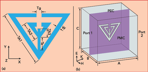
Figure 1 Asymmetric triangular electromagnetic resonator: element configuration (a) and as modeled in HFSS (b).
ANALYSIS OF METAMATERIAL STRUCTURE
Parametric Retrieval Analysis
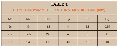
The folded ATER, shown in Figure 1, is composed of two equilateral triangles with open slots connected at their apexes opposite the slots. It is designed on a Rogers 6006 substrate with a thickness of 1.27 mm, relative dielectric constant (εr) of 6.15 and loss tangent (tanσ) of 0.0027, measured at 10 GHz. The remainder of the volume is air. Two kinds of boundary conditions, perfect electrical conductor (PEC) and perfect magnetic conductor (PMC), are modeled as shown in Figure 1b; the top and bottom faces of the box are PEC and the front and back faces are PMC. The structure was simulated with Ansoft HFSS using the finite element method. The geometric parameters are listed in Table 1, where Dg and mw are the gap width and width of the CPW, respectively, and rhole is the hole diameter of the pin array reflector.
Using the parametric retrieval method,15 the effective permittivity and effective permeability are calculated (see Figure 2). Figure 2a shows an electric resonance at around 6.2 GHz, where the value of the real part of the effective permittivity changes from positive to negative. Similarly, in Figure 2b, two magnetic resonances occur at around 3.5 and 5.7 GHz, with the strongest magnetic resonance occurring at 3.5 GHz. Both the second magnetic resonant frequency and electrical resonant frequency occur in the WLAN band. The lower band at 3.7 GHz is suitable for WiMAX.
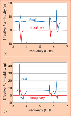
Figure 2 Retrieved effective permittivity (a) and effective permeability (b).
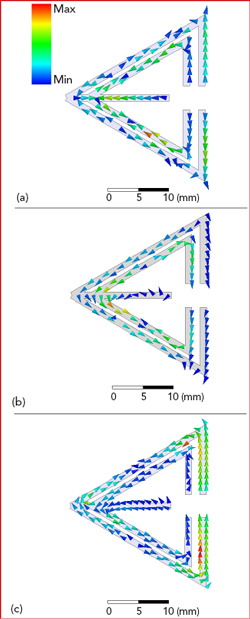
Figure 3 Eigenmode current distributions at 3.5 (a), 5.7 (b) and 6.2 GHz (c).
Eigenmode Analysis
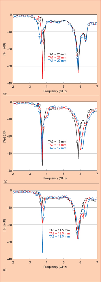
Figure 4 Simulated |S11| vs. TA1 (a), TA2 (b) and TA3 (c).
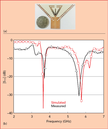
Figure 5 Fabricated antenna (a) and simulated vs. measured |S11| (b).
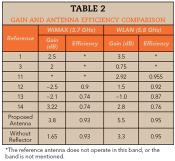
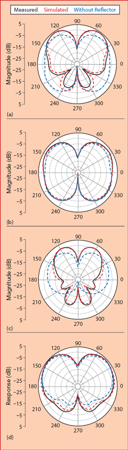
Figure 6 Simulated vs. measured radiation patterns in the WiMAX and WLAN bands: xoy plane at 3.7 GHz (a), yoz plane at 3.7 GHz (b), xoy plane at 5.8 GHz (c) and yoz plane at 5.8 GHz (d).
To characterize the intrinsic electromagnetic properties of the folded ATER, the HFSS eigenmode solver is set to a convergence precision of 0.1 percent with three eigenmodes. The eigenmode frequencies are 3.5, 5.7 and 6.2 GHz. Their current distributions are shown in Figure 3.
At the eigenfrequencies of 3.5 GHz and 5.7 GHz, the surface current is concentrated in the outside and inside triangular arms, respectively, as shown in Figures 3a and b. The main current forms a circle due to magnetic coupling, resulting in a negative permeability. At the eigenfrequency of 6.2 GHz, surface current is in three arms (see Figure 3c). The outside and inside triangular arms also display coupling with the magnetic field, but due to the asymmetrical structure, the surface currents from the outside and inside arm cancel on the middle arm. Therefore, the surface current in the middle arm is caused by coupling to the electric field, resulting in a negative permittivity; the electric resonance at 6.2 GHz, however, is weak.
ANTENNA DESIGN AND PARAMETER ANALYSIS
Varying one parameter and fixing the others, influences on the resonant frequencies were investigated in HFSS. Figure 4 shows three resonant frequencies, from low to high, corresponding to two magnetic couplings and one electric coupling. These are determined, independently, by the lengths of TA1, TA2 and TA3. As their lengths increase, the corresponding resonant frequencies decrease; the electrical resonance is sensitive to the length of the middle arm, as well.
In accordance with the current distribution of the ATER metamaterial structure, an equivalent circuit model can be obtained. It consists of a parallel equivalent capacitor, C, and equivalent inductor, L, where C is induced by coupling between the arms and L is produced by the arms, themselves. The values of C and L are different for the three resonances since the electrical arm lengths are unequal. Once these values are determined, the operating frequencies of the antenna are simply derived from
This formula provides an approximate working frequency since coupling between the ATER and pin array reflector is neglected. As noted, both the second magnetic resonant frequency and electrical resonant frequency occur in the WLAN band, and the lower operating band at 3.7 GHz is suitable for WiMAX.
EXPERIMENTAL RESULTS
A photograph of the antenna is shown in Figure 5a, fabricated on Rogers 6006 and fed by 50 Ω CPW. The metal pin array reflector, arranged linearly on both sides, enhances the gain in one plane. Coupling between the reflector and the outer triangular arm can be disregarded when the distance between them is larger than 3x the arm width. The measured and simulated |S11| are shown in Figure 5b. A small frequency difference between measured and simulated is observed, especially at higher frequencies. This is caused by antenna fabrication tolerances; however, the antenna is still operational in the WiMAX and WLAN bands.
The xoy plane and yoz plane radiation patterns at 3.7 GHz and 5.8 GHz are shown in Figure 6. In each sub-graph, the results of measured, simulated and simulated without pin array reflector are marked. Measured results agree well with simulation. The radiation pattern in the yoz plane is in the shape of a figure eight. The measured antenna gain is 3.8 dBi at 3.7 GHz and 5.5 dBi at 5.8 GHz using the gain comparison method. By adding the pin array reflector, the antenna gain is enhanced by approximately 2.15 dB at 3.7 GHz and 2.2 dB at 5.8 GHz in the xoy plane. In the yoz plane, the pin array reflector has a weak influence on the radiation pattern. A comparison with recently published antenna designs for WiMAX and WLAN applications is shown in Table 2.
Conclusion
A dual-band antenna for WiMAX at 3.7 GHz and WLAN at 5.8 GHz is excited by magnetic and electric resonances generated by a metamaterial structure. Antenna operation was analyzed using parametric retrieval analysis and eigenmode simulation. The operating bands can be tuned independently by changing the length of the triangular arms and center section. A metal pin array reflector improves the gain by more than 2 dB for each band in one plane. The 50 Ω CPW feed and single layer construction has the advantages of ease of fabrication and integration with RF circuits.
References
- Y. Xu, Y. C. Jiao and Y. C. Luan, “Compact CPW-Fed Printed Monopole Antenna with Triple-Band Characteristics for WLAN/WiMAX Applications,” Electronics Letters, Vol. 48, No. 24, November 2012, pp. 1519–1520.
- M. S. Alam and A. Abbosh, “Planar Pattern Reconfigurable Antenna with Eight Switchable Beams for WiMax and WLAN Applications,” IET Microwaves Antennas and Propagation, Vol. 10, No. 10, July 2016, pp. 1030–1035.
- T. Wu, X. W. Shi, P. Li and H. Bai, “Tri-Band Microstrip-Fed Monopole Antenna with Dual-Polarisation Characteristics for WLAN and WiMAX Applications,” Electronics Letters, Vol. 49, No. 25, December 2013, pp. 1597–1598.
- I. J. Garcia, J. C. Batchelor and J. M. H. Elmirghani, “Sectorised WiMAX Antenna for Future Vehicular Communications Systems,” IET Microwaves Antennas and Propagation, Vol. 4, No. 2, February 2010, pp. 210–218.
- A. K. Sharma, A. Mittal and B. V. R. Reddy, “Slot Embedded Dual-Band Patch Antenna for WLAN and WiMAX Applications,” Electronics Letters, Vol. 51, No. 8, April 2015, pp. 608–609.
- G. C. Y. Chen, K. K. M. Chan and K. Rambabu, “Miniaturized Yagi Class of Antennas for GSM, WLAN, and WiMax Applications,” IEEE Transactions on Consumer Electronics, Vol. 56, No. 3, October 2010, pp. 1235–1240.
- F. J. Herraiz-Martínez, G. Zamora, F. Paredes, F. Martin and J. Bonache, “Multiband Printed Monopole Antennas Loaded with OCSRRs for PANs and WLANs,” IEEE Antennas and Wireless Propagation Letters, Vol. 10, No. 1, December 2011, pp. 1528–1531.
- C. Zhu, T. Li, K. Li, Z. J. Su, X. Wang, H. Q. Zhai, L. Li and C. H. Liang, “Electrically Small Metamaterial-Inspired Tri-Band Antenna With Meta-Mode,” IEEE Antennas and Wireless Propagation Letters, Vol. 14, April 2015, pp. 1738-1741.
- C. Zhu, J. J. Ma, L. Li and C. H. Liang, “Multiresonant Metamaterial Based on Asymmetric Triangular Electromagnetic Resonators,” IEEE Antennas and Wireless Propagation Letters, 2010, Vol. 9, No. 1, pp. 99–102.
- D. K. Ntaikos, N. K. Bourgis and T. V. Yioultsis, “Metamaterial-Based Electrically Small Multiband Planar Monopole Antennas,” IEEE Antennas and Wireless Propagation Letters, Vol. 11, No. 3, September 2011, pp. 963–966.
- A. Gupta, S. K. Sharma and R. K. Chaudhary, “A Compact CPW-Fed Metamaterial Antenna for WLAN/Wi-Fi Applications,” IEEE International Symposium on Antennas and Propagation and USNC/URSI National Radio Science Meeting, July 2015.
- H. N. Quang and H. Shirai, “A Compact Tri-Band Metamaterial Antenna for WLAN and WiMAX Applications,” IEEE International Conference on Electromagnetics in Advanced Applications, October 2015.
- M. A. Abdalla, “A Dual Mode CRLH TL Metamaterial Antenna,” IEEE Antennas and Propagation Society International Symposium, September 2014.
- B. D. Bala, M. K. A Rahim, N. A. Murad and R. Dewan, “Wideband Metamaterial Antenna Employing SRR Loading for WiMAX and WLAN Operations,” IEEE Asia-Pacific Conference on Applied Electromagnetics, December 2015.
- Z. Szabo, G. H. Park, R. Hedge and E. P. Li, “A Unique Extraction of Metamaterial Parameters Based on Kramers-Kronig Relationship,” IEEE Transactions on Microwave Theory and Techniques, Vol. 58, No. 10, September 2010, pp. 2646–2653.