
The 5G mobile communications standard is a big leap forward from its predecessor, 4G. The focus is no longer just sub-6 GHz for communications, rather on multiple frequency bands that accommodate different purposes in the communications chain. While most of the legacy frequency bands already in use fall into standard test equipment frequency bands, i.e., 10, 20 and 40 GHz, the 5G spectrum from 37 to 43.5 GHz has created a new requirement. Test & measurement (T&M) equipment manufacturers have responded to the need for broader frequency coverage by releasing equipment that measures to 43.5 GHz. However, a measurement is only as good as the components that exchange signals with the test equipment, and these components are only as good as their connectors. Accurate measurements to 43.5 GHz require precision components that leverage the 2.92 mm (K) connector currently used to 40 GHz, while providing mode-free performance to 43.5 GHz and a clear path of traceability.
WHY 43.5 GHz?
While many of the initial 5G deployments are using sub-6 GHz spectrum, the mmWave range (i.e., 24 GHz and above) has the advantage of providing immense bandwidth. Many countries are allocating spectrum in the 37 to 43.5 GHz range (see Figure 1). In June 2018, the U.S. FCC proposed using 42 to 42.5 GHz for broadband or fixed wireless service, while Brazil and Mexico have similar proposals for mobile broadband within the 37 to 43.5 GHz range. Japan and the European Union have proposed 40.5 to 43.5 GHz for similar mobile broadband functionality. China may be the biggest driver for adoption of the frequencies up to 43.5 GHz. China’s Ministry of Industry and Information Technology has been at the forefront of 5G for R&D testing.1 In addition to proposing spectrum for 5G, China has held R&D trials leading to product trials, which began in late 2018.
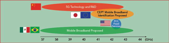
Figure 1 5G mmWave spectrum by country and application.1
This extension of frequencies has been quietly incorporated by many T&M companies over the last few years, adding this frequency option to existing and new products. One of the many aspects of providing 43.5 GHz coverage is the connector interface, i.e., the link between the user and the test equipment. Currently, there are two approaches to getting a user to 43.5 GHz:
2.4 mm connectors on the test equipment - This option has a dual purpose. Foremost, it supports performance to 50 GHz on the connector and establishes traceability. However, one issue with this approach is that the user must replace all cabling, adapters, calibration kits and other components to those with 2.4 mm connectors. This is costly, as 2.4 mm components are usually more expensive than 2.92 mm solutions. Another issue is that many devices being tested have the 2.92 mm K connectors, meaning users must add an adapter to convert from the 2.4 mm connectors on the test equipment to 2.92 mm connectors on the device being tested. While most manufacturers with 2.4 mm connectors offer adapters to 2.92 mm, unless the adapter is rated or specified to 43.5 GHz on the 2.92 mm side, the performance may not extend to 43.5 GHz, limited by over-moding, the creation of modes on the connector. This will be discussed below.
2.92 mm connectors on the test equipment - The second approach uses 2.92 mm connectors on the instrument, with the caveat that traceability is not available from 40 to 43.5 GHz, and the specified performance is “measured.” The drawback with this approach is the connectors are most likely not tested individually and are part of a “catch all” approach to defining the instrument’s specifications.
OVER-MODING
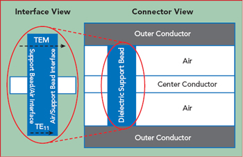
Figure 2 Over-moding at the dielectric support bead.
Two of the most important aspects of the connector’s electrical performance are its frequency scalability and whether it supports the required performance to 43.5 GHz. To achieve optimal performance, mode propagation in the connector should be prevented. For the K connector, with 2.92 mm dimensions, only the desired transverse electromagnetic (TEM) mode can theoretically propagate up to about 46 GHz. Practically, the cutoff frequency is lower: dielectric support beads are required to make the connector mechanically stable, and because the wavelength shrinks in the dielectric, compared to air, additional modes can propagate below 46 GHz. This is why K connectors are typically specified to 40 GHz.
Above the cutoff frequency, an additional mode - TE11, which is not transverse - can propagate, with other modes propagating at higher frequencies.2 This is a problem, as energy from the input signal can transform between the modes, launched by small imperfections on the bead surface (see Figure 2). Since the modes have different impedances and phase velocities, this leads to a resonance in transmission or reflection. Over-moding within the connectors will reveal itself during measurements, clearly visible in a transmission measurement of the connector, seen as a large attenuation spike within a small bandwidth (see Figure 3). Once the frequency of the resonance is passed - the coupling of energy between modes is not as efficient - the trace will return back to the original transmission path.
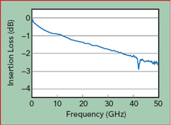
Figure 3 Generic over-moded transmission response at 42 GHz.3
Over-moding can be avoided by reducing the dielectric bead circumference, optimizing the bead impedance and reducing the chance of energy coupling into the mode, by tightening other tolerances, for example. Assuming a manufacturer overcomes all the obstacles and designs a 2.92 mm connector that will not over-mode to beyond 43.5 GHz, will that provide sufficient confidence in the measurements? The answer varies from application to application, based on how stringent the test specifications. This information can be shown in datasheets, where the performance is qualified as a hard or measured specification.
WHY TRACEABILITY IS IMPORTANT
A term used with the electrical specifications in the 40 to 43.5 GHz region of a test instrument is “measured.” A measured or characteristic specification refers to measurements that provide a set of data that can be quantified with some level of confidence and used to represent all units. While this is not an uncommon approach to setting electrical specifications and is becoming more prevalent, the difference between the specifications below 40 GHz and the approach using measured data to define the specifications above 40 GHz is traceability. Below 40 GHz, the uncertainty budget is clearly defined through an unbroken chain of traceability; measurements between 40 to 43.5 GHz generally do not have the same confidence. For manufacturers, the uncertainty may be important, as the measurement of a product will establish whether it passes or fails a test specification.
While traceability is the path to establishing a solid uncertainty budget, it is much more: a quality assurance system tied to a recognized national metrology institute, like NIST or METAS. Not all connectors can be traceable, such as the SubMiniature version A (SMA) connector. Although used extensively, the SMA is not usually considered traceable because of its dielectric interface, lack of standardization and low repeatability. This is why SMA connectors do not yield precision measurements.
Fortunately, the K connector’s basic characteristics can support traceability and, with careful design, can achieve reasonable and documentable uncertainties to 43.5 GHz. The most fundamental aspect of traceability for the connector is impedance, which depends on the dimensional assessment and control in airlines used to measure the connectors. Dimensional measurements are performed with traceable tools such as laser micrometers, coordinate measuring devices and air gages. Once these measurements have been made, the next step is to link airline performance through calibration kits and other components to an individual connector (see Figure 4). Some of the measurement quantities used to assess the connectors are outlined in the IEEE P287 Standard for Coaxial Connectors.4
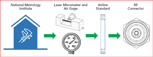
Figure 4 Traceability path for RF connectors.
TRACEABLE K CONNECTOR
To address the challenges designing a 43.5 GHz connector with traceability, Anritsu created a new connector functionality known as Extended-K™. Extended-K components with 2.92 mm connectors do not over-mode, provide traceable specifications to 43.5 GHz and avoid the costly investment to move a measurement system to 2.4 mm connectors. Anritsu offers a complete K connector system for 43.5 GHz measurements, including test port cables, adapters for 2.4 mm connectors, a portable thru-open-short-load calibration kit in both male and female gender and Anritsu’s ShockLine™ vector network analyzers with Extended-K functionality. Anritsu’s adapters are traceable and enable the user to quantify the uncertainty budget.
References
- “5G Spectrum Vision,” 5G Americas, February 2019, www.5gamericas.org/files/4015/4958/3330/5G_Americas_5G_Spectrum_Vision_Whitepaper.pdf.
- B. Williams, “ANAMET Report 044: Overmoding Transmission Characteristics of Type-N Connector 7 mm Line Between 18 and 26.5 GHz,” National Physics Laboratory, Middlesex, U.K., May 2004, resource.npl.co.uk/docs/networks/anamet/members_only/publications/report_044.pdf.
- R. Fuks, “New Dielectric Bead for Millimeter-Wave Coaxial Components,” Microwave Journal, May 1, 2001, www.microwavejournal.com/articles/3205.
- “IEEE Standard for Precision Coaxial Connectors (DC to 110 GHz),” IEEE Instrumentation and Measurement Society, New York, N.Y., 2007.