
To realize high performance mmWave communications, beamforming antenna systems will need to be smarter, faster, smaller, lower power, cost less, have lower latency and be easier to integrate than current technologies. Much like with previous telecommunication systems, integrating important processing and signal conditioning functions will enable more cost-effective and compact mmWave beamforming antennas. The development of complex mmWave RF and analog hardware for 5G and tactical communications will initiate an inevitable evolutionary trend in digital communications, with digital processing eventually supplanting analog. The recent emergence of an all-digital antenna approach leveraging antenna processing units (APU) and ASICs could accelerate this trend, further reducing the time-to-market for highly anticipated multi-data path mmWave 5G and tactical communications.
The limited bandwidth and abundant congestion of sub-6 GHz spectrum has spurred extensive investigation into additional swaths of spectrum from 20 GHz to over 100 GHz (i.e., mmWave) for next-generation wireless communication systems. Originally sought after by industrial and commercial organizations for 5G, interest in the mmWave spectrum has expanded to encompass military and aerospace applications, such as tactical communications.1–3 Beyond a manifold increase in the available bandwidth, compared to the sub-6 GHz spectrum, mmWave frequencies present a variety of benefits, as well as a range of design and operational challenges.
The size of antennas and transmission lines at mmWave frequencies are smaller than those at sub-6 GHz, owing to the shorter physical wavelength, with the smaller size enabling much more compact hardware. Moreover, the beamwidths of mmWave antennas are much narrower, hence more spatially selective than lower frequency antennas. These benefits come with the trade-off of higher RF path loss and less efficient transmission. Additionally, the atmospheric attenuation at mmWave frequencies is much higher than in the sub-6 GHz bands. The reduced signal dispersion limits interference, jamming and potential snooping to roughly line-of-sight, offering benefits for tactical communications.
To overcome the greater RF path loss and atmospheric attenuation, it is widely accepted that the use of beamforming antenna technologies is one of the most viable solutions.4–11 Certain beamforming designs also enable active antenna features, such as active electronically scanned arrays (AESA), which have been instrumental in jamming, anti-jamming, SATCOM and aerospace communications systems.
Many research, industry and military organizations are investigating and developing mmWave active antenna technologies that can be deployed in a reliable and cost-effective manner. Cost, size and complexity are significant factors for mmWave communications systems, especially for 5G, as the range and coverage provided by small cells is intrinsically less than the prior generation macro cells, meaning operators need to deploy many more 5G small cells in denser environments. This R&D involves the development of analog, hybrid and digital beamforming systems and their relative feasibility. This article discusses these methods and concludes an all-digital antenna approach leveraging digital beamforming is the best and inevitable architecture.
BEAMFORMING AND MIMO
Beamforming is the manipulation of an antenna pattern to control the mainlobe and sidelobe responses. A variety of methods can be used to accomplish this, though the dominant method discussed in this article is with multi-element antennas with phase control or delay. At a certain carrier frequency and with a properly designed multi-element antenna, a phase shift calculated for each antenna element can change or “steer” the antenna pattern. Beam steering with phase shifts can be used with linear antenna arrays to change the azimuth antenna pattern, and 2D antenna arrays can control the pattern in both azimuth and elevation.
Beamforming benefits mmWave communications since mmWave antenna systems typically have narrow antenna patterns with high attenuation, and multi-element antennas with active beamforming can increase the gain of the aperture and steer the beam toward a desired target to achieve the maximum signal quality. With sufficiently sophisticated beam steering technology, active beam steering enables a mmWave communications link to have a longer range and greater throughput.
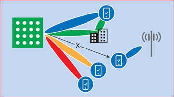
Figure 1 MIMO can increase capacity and coverage in dense urban and in-building environments by pointing beams and creating nulls. Source: Ericsson.12
A related topic is using spatial diversity with multi-element antennas to create more than one signal path from a given antenna array to the user, a method known as MIMO (see Figure 1). The ability to transmit and receive multiple spatial streams allows for additional communication to occur simultaneously, either augmenting the throughput to a single user (SU-MIMO) or multiple users (MU-MIMO). Employing MIMO technology is another method to enhance the throughput of 5G communications and connect larger numbers of users simultaneously, without deploying additional cells. These techniques generally best serve dense urban environments and require multiple radio channels. In the case of mmWave, extremely narrow beamwidths, high atmospheric attenuation and the likelihood that multipath and reflections will suffer from high attenuation limit the potential gains for MIMO technology.
BEAMFORMING TYPES
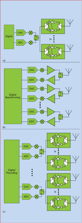
Figure 2 Simplified block diagrams of analog (a), digital (b) and hybrid beamforming (c). Source: Analog Devices.8
The original analog beamforming antenna systems used fixed delays created by phase shifters at each antenna element to create a static beam pattern designed for a single frequency. Advancements of this approach added switches to select among several fixed phase shifters, creating a set of pre-designated antenna patterns. Further advancements adopted adjustable phase shifters at each antenna element, enabling a flexible, actively controlled phased array antenna, i.e., AESAs. With these beamforming antennas, the digital signals are usually created at baseband using digital-to-analog converters (DAC), converted to RF via frequency conversion and split to feed the transmit/receive (T/R) modules with phase shifters at each element. The received signal follows the reverse path; after down-conversion, the RF is digitized with an analog-to-digital converter (ADC) for processing. The T/R module contains the phase shifter, amplitude control and power and low noise amplifiers. This architecture, known as analog beamforming, requires a separate control signal for each phase shifter at each of the antenna elements and is limited to steering a single spatial beam (see Figure 2a).
A more recent approach uses DACs and ADCs directly connected to each T/R module. This method, known as elemental digital beamforming, enables the beamforming algorithms and digital baseband processing to be entirely implemented with robust digital hardware, eliminating the need for sensitive analog RF phase shifters used with analog beamforming. Digital processing is capable of creating multiple spatial streams simultaneously, such that a single antenna array can dynamically create MIMO data streams and beams optimized in real-time for the user and load requirements (see Figure 2b).
The biggest challenge for digital beamforming is power consumption. Analog beamforming requires lower DC power. However, since each analog beamformer only supports a single beam - and a digital beamformer enables multiple concurrent beams - digital beamforming is favored in high density environments demanding low latency and uncongested communication. Digital beamforming is particularly attractive for infrastructure networks supporting mobile users.
As the data conversion requirements of elemental digital beamforming systems are the bottleneck for provisioning digital beamforming solutions, cost and power considerations for mmWave antenna arrays have led to an interim approach using hybrid beamforming. Although there are various methods, hybrid beamforming generally combines the analog beamforming phase shifting topology for a subset of the antenna elements - with RF phase shifters, attenuators, low noise and power amplifiers, switching and circulators/isolators still used - and each subarray is driven by data converters with some level of digital precoding (see Figure 2c). With this approach, the processing load on the digital electronics and power consumption are less than with elemental digital beamforming. Hybrid beamforming typologies can be designed to allow for multiple spatial streams, although it is less flexible than elemental digital beamforming since the number of beams is limited to the number of hybrid subsets.
To realize elemental digital beamforming for mmWave multi-element antennas, the electronics must be capable of processing Gbps of throughput in real-time, while minimizing latency. 5G, for example, requires signal bandwidths up to 400 MHz. Elemental or all-digital beamforming requires that modulation, demodulation, conversion, spatial processing and beamforming processing occur in real-time, or at least fast enough to track a mobile user. Therefore, more intelligence is required with all-digital beamforming antennas than just baseband processing and beamforming, and these added digital functions are energy expensive. If realized as a discrete module, they add significant complexity to the physical layout, increasing size and, likely, cost. This is especially true if software-defined logic, such as FPGAs, is used. At this point, thermal management and power management become significant design considerations and high density and high throughput board-to-board and cable-to-board interconnects may be required. To avoid this complexity, a fully integrated ASIC with multi-channel wide bandwidth data conversion and efficient FinFET CMOS digital processing is required to meet the promise of digital beamforming. IQ-Analog has defined a family of APUs to service this emerging market need.
While an analog beamforming antenna system is less complicated and is generally more power efficient than comparable hybrid or digital beamforming antennas, the size and cost of discrete analog components and interconnects pose complexity issues as the antenna array grows beyond a small size. For antenna arrays greater than 4 x 4 or 8 x 8, hybrid beamforming or digital beamforming offer size, weight and cost advantages. Operators typically desire minimal changes to the form factor and power of their equipment, to keep leasing and operational costs down. While 5G mobile handsets can operate with roughly the same data and power efficiency as with 4G, 5G mmWave antenna infrastructure must be deployed at roughly 10x greater density and deliver 10x greater data capacity, which demands the most efficient multi-beam digital antenna processors. The unique digital antenna processing needs of mmWave antennas must be addressed using the most highly integrated and streamlined methods possible, meaning a unique ASIC composed of high channel count data converters, digital antenna processing and high speed digital I/O systems.
ALL-DIGITAL ANTENNAS
With greater component integration, the hybrid and digital topologies become more feasible, enabling mmWave beamforming and MIMO antennas to have a greater number of antenna elements. This shift enables more capable and flexible antenna systems that can provide higher gain with SU-MIMO or MU-MIMO operation. The promise of these architectures hinges on the performance of the digital and conversion electronics, i.e., the ability of the direct RF sampling and direct digital synthesis to address the full capacity of the mmWave spectrum. Otherwise, additional frequency translation hardware will be required, increasing complexity and reducing flexibility.
These trade-offs materialize as modem and beamforming technologies designed strictly for a single application, which may be infeasible for commercial and military manufacturers who want more flexible and capable solutions to support complex licensing and geographic restrictions. Direct RF sampling enables more flexible use of spectrum and does not limit a mmWave antenna to set 28 or 39 GHz frequency bands; any spectrum within the capability of the RF sampling hardware is accessible. Direct RF sampling is ideal when paired with software-defined radios (SDR); however, it presents a challenge for the data converters to meet the performance requirements.
With the specifications for mmWave 5G and tactical communications not fully defined and likely to change, the trend is for modem suppliers to provide SDR solutions rather than fixed modems. As the mmWave standards evolve, the SDR can be reprogrammed to meet the updated standard, whether for 5G or military applications. Modular scalability at the antenna elements and beamforming hardware is desirable for mmWave 5G base stations, to provide the flexibility to be upgraded without complete and costly hardware replacement. This is critical for operators, as the number of 5G mmWave base stations will be roughly 10x the number of 4G base stations to provide similar coverage. The number of 5G mmWave base stations may actually reach the same order of magnitude as mobile 5G handsets.
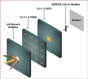
Figure 3 mmWave all-digital antenna.
To take full advantage of SDR technology, full spectrum conversion and digital beamforming APUs are needed, an architecture dubbed all-digital antennas. The all-digital antenna, a digital beamforming phased array that supports several wide bandwidth MIMO beams, integrates an antenna array, RF front-end (RFFE) SoC and multi-chip module containing an APU and modem using a high speed converter interface, such as JESD204B (see Figure 3).13 The APU contains digital down-conversion with decimation and up-conversion with interpolation. Ideally, the all-digital antenna beamforming function is an ASIC rather than an FPGA or FPGA-ASIC hybrid. Though feasible in each configuration, building an FPGA-based all-digital antenna requires a greater footprint and significantly higher power consumption, with greater latency and likely higher cost. The best configuration would be a monolithic FinFET ASIC, with the most efficient data converter and digital processing.
CONCLUSION
Though the trend toward integration and all-in-one ICs was a slow process for prior generations of wireless communications (i.e., 2G, 3G, 4G and Wi-Fi), the path toward ASIC-based APUs and a more efficient all-digital antenna for 5G will be accelerated by 5G’s tremendous market demand. High performance full spectrum conversion APUs have already been fabricated in FinFET CMOS, and the underlying technology exists to realize multi-channel APU derivatives capable of the several GHz of addressable signal bandwidth needed for 5G. Designed with flexibility and programmability, these APUs can be readily adapted to a range of mmWave applications, such as 5G, tactical communications, autonomous vehicle radar and V2X and LEO SATCOM.
References
- “mmWave for Army Tactical Communications,” SBIR Funding Topic, November 2018, www.sbir.gov/sbirsearch/detail/1531631.
- S. Carlson, “Raytheon Tapped by DARPA for High Frequency Digital Communications Research,” UPI, November 6, 2018, www.upi.com/Raytheon-tapped-by-DARPA-for-high-frequency-digital-communications-research/3351541528087/.
- “Military Communications Market: Technological Advancements & Propelling Demand for C4ISR Systems to Drive Growth in Developing Markets: Global Industry Analysis (2013-2017) and Opportunity Assessment (2018-2028),” Future Market Insights, June 2018, www.futuremarketinsights.com/reports/military-communications-market.
- “Millimeter-Wave Beamforming: Antenna Array Design Choices & Characterization,” Rohde & Schwarz, https://scdn.rohde-schwarz.com/ur/pws/dl_downloads/dl_application/application_notes/1ma276/1MA276_2e_Beamform_mmW_AntArr.pdf.
- T. S. Rappaport et al., “Overview of Millimeter Wave Communications for 5G Wireless Networks-with a focus on Propagation Models,” IEEE Transactions on Antennas and Propagation, November 2017.
- “The Military Communications Market: 2015-2030 - Opportunities, Challenges, Strategies & Forecasts,” HTF Market Inteligence, April 2015, www.htfmarketreport.com/reports/17351-the-military-communications-market.
- C. Scarborough et al., “Beamforming in Millimeter Wave Systems: Prototyping and Measurement Results,” 2018 IEEE 88th Vehicular Technology Conference, August 2018.
- T. Cameron, “Bits to Beams: RF Technology Evolution for 5G Millimeter Wave Radios,” Analog Devices, www.analog.com/media/en/technical-documentation/tech-articles/Bits-to-Beams-RF-Technology-Evolution-for-5G-mmwave-Radios.pdf.
- P. Sagazio et al., “Architecture and Circuit Choices for 5G Millimeter-Wave Beamforming Transceivers,” IEEE Communications Magazine, Vol. 56, No. 12, December 2018.
- J. Zhang et al., “5G Millimeter-Wave Antenna Array: Design and Challenges,” IEEE Wireless Communications, Vol. 24, No. 2, April 2017.
- A. H. Naqvi and S. Lim, “Review of Recent Phased Arrays for Millimeter-Wave Wireless Communication,” Sensors, September 21, 2018, www.ncbi.nlm.nih.gov/pmc/articles/PMC6211090/.
- P. von Butovitsch et al., “Advanced Antenna Systems for 5G Networks,” Ericsson, www.ericsson.com/en/white-papers/advanced-antenna-systems-for-5g-networks.
- “ADI JESD204B Survival Guide,” Analog Devices, www.analog.com/media/en/technical-documentation/technical-articles/JESD204B-Survival-Guide.pdf.