

Microwave mixers translate the frequency of electromagnetic signals. This functionality is vital for an enormous number of applications such as military radar and surveillance, RF communications, radio astronomy and biological sensing. Despite their ubiquity, however, microwave frequency mixers remain some of the most misunderstood components in an RF/microwave engineer’s toolbox. This basic introduction provides insight into what some may consider the “dark art” of microwave mixers.
What is a mixer?
A frequency mixer is a 3-port RF electronic circuit. Two of the ports are “input” ports and the remaining port is an “output” port. An ideal mixer “mixes” the two input signals such that the output signal frequency is either the sum or difference of the inputs. In other words:
fout = fin1+ fin2 (1)
The 3 mixer ports are the Local Oscillator (LO) port, the Radio Frequency (RF) port, and the Intermediate Frequency (IF) port. The LO port is typically driven with either a sinusoidal continuous wave (CW) signal or a square wave signal. The choice to apply a CW or square wave signal depends on the application and the mixer. Conceptually, the LO signal acts as a “gate” or a “switch” in the sense that the mixer can be considered “ON” when the LO is a large voltage and “OFF” when the LO is a small voltage. The LO port is usually an input port. The other 2 ports of the mixer, the RF and IF, can be interchanged as either the second input or the output; the actual configuration depends on the application.
When the desired output frequency is lower than the second input frequency, the process is called downconversion; the RF is the input and the IF is the output. The relationship between input and output frequencies is given by:
fIF = |fLO - fRF| (2)
On the other hand, when the desired output frequency is higher than the second input frequency, the process is called upconversion, where the IF is the input and the RF is output, i.e.:
fRF = fLO + fIF (3)
A frequency domain representation of downconversion and upconversion is illustrated in Figure 1. Note that for upconversion, the sum and difference frequencies (fRF1 and fRF2) in the frequency domain implies that both are available at the RF output port, as indicated in Equation (3). This type of upconversion is known as double sideband upconversion. Single sideband upconversion is also possible, in which case either the sum or the difference frequency is intentionally canceled inside the mixer. Mixers that perform this more sophisticated function are called single sideband (SSB) upconverters (or SSB modulators).
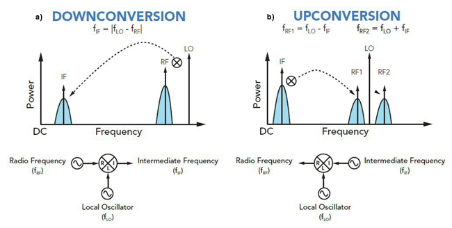
Figure 1. Definitions of downconversion (a) and upconversion (b).
As Figure 1 shows, IF and RF signals tend to be information bearing signals (as denoted by the broadened spectra surrounding the RF and IF center frequencies). During frequency conversion, the information carried by the RF or IF signal is frequency translated to the IF or RF output. Therefore, mixers perform the critical function of translating information in the frequency domain.
In principle, any nonlinear device can be used to provide the “gate” function for a mixer circuit. As it happens, only a few nonlinear devices make “good” mixers. The devices of choice for modern mixer designers are Schottky diodes, GaAs FETs and CMOS transistors. The choice depends on the application. FET and CMOS mixers are typically used in higher volumes where cost is the main driver and performance is less important. For the more challenging applications, Schottky diode mixers are used almost exclusively. A Schottky diode a semiconductor diode formed by the junction of a semiconductor with a metal. It has a low forward voltage drop and a very fast switching action that enhances its mixer performance. For simplicity, the remainder of this discussion focuses on diode mixers, but the principles may be generally applied.
Single Diode Mixer: Ideal Commutator vERSUS Realistic Diode
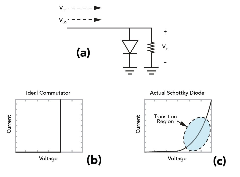
Figure 2. Simple single ended mixer (a) I-V characteristics for an ideal commutator (b) and a realistic Schottky diode (c).
The simplest mixer consists of a single diode as shown in Figure 2a with a large signal LO and a small signal RF combine at the anode. An “ideal” single diode mixer assumes that the LO is significantly stronger than the RF such that only the LO affects the diode’s transconductance. Also assumed is that the diode switches instantaneously as shown in Figure 2b. Devices with instantaneous transconductance switching are called ideal commutators and yield theoretically optimal diode mixer performance.
The “mixing” process is due to the switching response of the diode I-V curve to the strong LO signal. As the diode is opened and closed by the LO, the smaller signal RF is “chopped”. The Fourier components of the output signal from an ideal commutating (or switching) mixer diode (see Figures 3a and 3c) follow the relation:
fIF = nfLO + fIF (4)
where n is odd.
Unfortunately, the transfer function of the ideal commutator can never be achieved in the real world. Actual Schottky diodes possess some amount of “turn-on” transition as shown in Figure 2c. Moreover, the RF modulates the diode transconductance to some extent, even if the RF is very small. The combination of realistic diode I-V characteristics and transconductance modulation by the RF signal causes additional mixing products (often referred to as “spurs”). Thus real diodes produce all possible harmonic mixing components! The time domain signal and associated frequency spectrum generated by a realistic Schottky diode are shown in Figures 3b and 3d. Mathematically, the frequency components generated by a single diode are given by:
fIF = nfLO + mfIF (5)
where n and m include all integers.
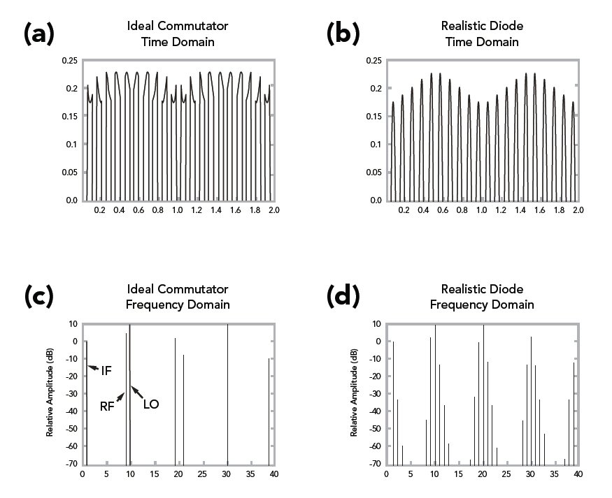
Figure 3. Time and frequency domain comparison of a single ended mixer with ideal and realistic diode switching characteristics.
Because there is one desired output frequency (when n=1 and m=1), the existence of all other harmonic terms creates significant problems. Elimination of these distortion products is a key goal in mixer design.
This simplified analysis illustrates several important attributes of frequency mixers:
1. “Mixing” is caused by the switching behavior of the diode.
2. The majority of unwanted harmonics are caused by nonlinear intermodulation of the RF and LO signals in the transition region of the diode; therefore, the best mixers use diodes that closely approximate ideal commutators.
3. The lower the RF power, the better the spurious performance (since the LO then controls the diode transconductance more effectively).
Mixer Balance
High performance mixers are designed using four or eight diodes. The evolution of the mixer circuit from the single diode unbalanced type to the multi-diode balanced type is described by Marki1 and summarized here. High performance mixers are designed using four or eight diodes and make use of sophisticated circuit designs with symmetry to create “balance”. In fact, virtually all commercially available mixers make use of some kind of mixer balancing. Mixer balancing offers several advantages: inherent isolation among all mixer ports (and hence band flexibility), cancellation of most intermodulation products, common mode signal rejection and improved conversion efficiency. Extra circuitry is needed to route and separate (i.e multiplex) input and output signals from the diodes. In single diode mixers this extra circuitry consists of a combination of passive coupling, power division, and filtering. It is difficult to create wideband single diode mixers with independent RF, LO, and IF bands since the multiplexing circuitry is frequency specific. Moreover, such circuitry causes extra losses that reduce mixer efficiency.
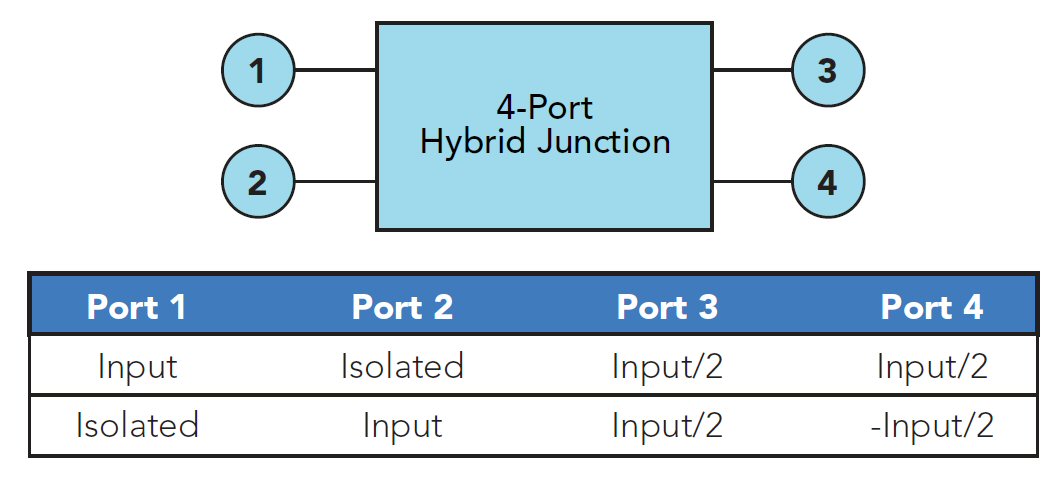
Figure 4. Schematic and I/O table for a 4-port hybrid junction.
To solve this problem, wideband single-balanced mixers with low loss and independent input and output frequency bands may be created using a classic four port hybrid junction. A hybrid junction (i.e. “magic tee” or the 180o hybrid), shown in Figure 4, is a two input, two output, four- port circuit that provides isolation between input ports and equal power division at the output ports. This isolates the input LO and RF sources from one another, thus providing frequency band independence and equal power division to the load. Note that the output signals are differentially phased (i.e. 180o phase shifted) when a signal is input to port 2. Output signals are in phase for inputs to port 1. The hybrid junction provides a natural method to create the single balanced mixer shown in Figure 5.
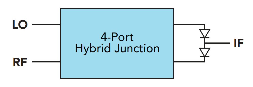
Figure 5. Single balanced mixer with 4-port hybrid junction.
Additionally, two diodes are used instead of one. The key features of the single balanced mixer include:
1. Isolation (and hence frequency independence) between RF and LO ports.
2. 50 percent reduction in the total number of intermodulation products.
3. Common mode noise cancellation (good for noisy LO).
4. Higher conversion efficiency than a single diode mixer.
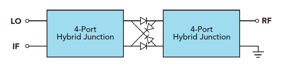
Figure 6. Double balanced mixer.
Furthermore, two single balanced mixers can combine to form a double balanced mixer as shown in Figure 6. In this case, hybrid junctions are placed on both the RF and LO differential ports and the IF is obtained at the in phase port of the hybrid junction. Reciprocity of the hybrid junction allows this type of interconnection.
Detailed analysis reveals that for the double balanced mixer, only ODD n and ODD m harmonic spurs can survive at the IF port.2 Therefore, mixer double-balancing has the benefit of reducing nearly 75 percent of possible spurious at the IF port. Due to conservation of energy, double balanced mixers tend to have better conversion efficiency than single ended or single balanced mixers, since energy cannot spread into the EVEN order harmonics.
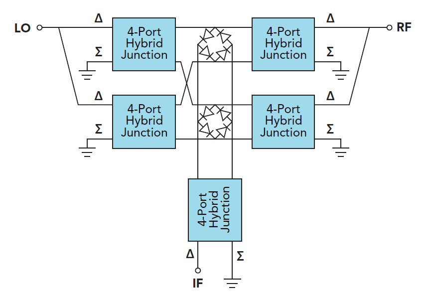
Figure 7. Doubly double balanced mixer (aka triple balanced mixer).
A more complex mixer circuit is created using two double balanced mixers driven in a push-pull configuration (see Figure 7). This “doubly double balanced” mixer has received the ill-conceived title of “triple balanced” mixer. Some of the key features of the triple balanced mixer are overlapping RF, LO and IF bands and higher spurious suppression.3
Mixer Performance Metrics
What makes a “good” mixer? Well—lots of things. Some of the criteria by which to judge, and ultimately choose, a mixer are:
Conversion Loss
The most important mixer metric is conversion loss, which is defined as the difference in power between the input RF power level and the desired output IF frequency power level, or
CL = PRF - PIF (6)
where PRF and PIF are in dBm and CL is in dB.
For example, if the input RF is -10 dBm and the downconverted IF output signal -17 dBm, then the conversion loss is 7 dB. The theoretically optimum conversion loss for a passive diode mixer is 3.9 dB and can be calculated using equations derived by Henderson.4 Typical values of conversion loss range from about 4.5 to 9 dB, depending on the mixer; the additional losses are caused by factors such as transmission line losses, balun mismatch, diode series resistance and mixer (im)balance. In general, double balanced mixers have less conversion loss than triple balanced mixers because of circuit losses. Another important trend is that wider bandwidth mixers tend to have higher conversion loss in part due to the difficulty in maintaining circuit balance over the entire bandwidth.
Conversion loss is the benchmark mixer metric because it correlates closely with other metrics like isolation and 1 dB compression. Experience shows that for a mature mixer design, a single conversion loss measurement will indicate the quality of the unit. If the conversion loss of a unit is within a narrow specification, all other performance metrics will also meet specifications. The converse is not necessarily true however; it is possible to have good isolation and poor conversion loss, for example.